
Electrical
Oil Pressure Sentinel
Full Throttle
Headlights and Starting
Theft-Proofing Your VW
Headlight Telltale
Steering Column Update
Electronic Regulator
Why Have an Ammeter?
Electronic Idle Control
True Volts
VW’s New Modular Wiring System
Beetle Regulators
A Broad Look at Fuseboxes
Glen’s Wiring Tricks
Showing Your Colours
Reception Problems With Car Radios
Light Improvements
From 6 volts to 12 volts
Night into Day
Wiper Resistor
VW Diagnosis plug
How to modify those windscreen washers so they actually work Pt.1
How to modify those windscreen washers so they actually work Pt.2
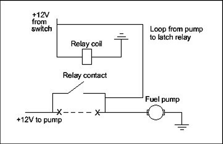
Oil Pressure Sentinel
By Rod Young
November 1987
If you drive your car in competition, or even very hard on the street, you won't have time to look at the oil pressure gauge all the time, if one is fitted, and the stock warning light may not be sufficiently noticeable when you're in a four-wheel drift at full throttle through a tight corner on the dirt.
If a loud piezoelectric horn, available from electronic supply outlets, is fitted according to the diagram, you'll have no doubt whatsoever when your oil pressure goes away, a fairly common occurrence with air-cooled VWs. The advantage with this arrangement is that the horn does not sound unless there is a power supply from the generator or alternator; ie. unless the engine is running, otherwise the noise would be unbearable with the ignition alone switched on.
Fitting is very easy, the horn being attached to both oil pressure and charge warning lights. It is best done using ‘piggyback’ adapter terminals pushed onto the warning light holders. The horn itself can be either screwed down, stuck with silicone sealer or attached with a cable tie, depending on the design of its case.

Some of these horns are polarised; that is, they will only work in one direction. The one I fitted to a rally Beetle recently worked in either direction, so that it also sounds if there is a failure in the charging system (when there IS oil pressure), which isn't a bad feature either. It also lets out a wail whenever the engine is switched off, to make you aware of its presence! If you want only an oil pressure warner, simply fit a diode in series leading from the blue D+ wire to the red wire of the horn.
The horn has proved itself on more than one occasion in rally driving, protecting a very powerful and expensive engine. However, you don't need to drive in a rally to experience loss of oil pressure - due to its flat, shallow sump, even a stock Beetle with oil up to the top mark on the dipstick can run out of oil with enthusiastic cornering, and this simple audible warning device will let you know about it.
Full Throttle
By Rod Young
December 1987
If you want to wring the last few Watts out of your engine at full throttle, one thing you can do is to immobilise the charging system so that there is less of a drag on the crankshaft due to the generator or alternator. There isn't much extra power to be gained, but every little bit helps and there's only a small chance of getting a flat battery, as most people use full throttle for only a few seconds at a time.
The way to do this is to interrupt the field current supply, ie. the current being switched by the voltage regulator to the field coils. On German cars, this is a green wire, and the terminals are marked "DF". If you fit a micro switch to the throttle linkage that is actuated at full throttle, you've done it already. Just break the green DF wire and attach both ends to the "common" and "normally closed" terminals of the micro switch respectively. An added bonus is that you get an indication of full throttle being reached as the charge warning light comes on! It is satisfying to know that you're getting all the power available.
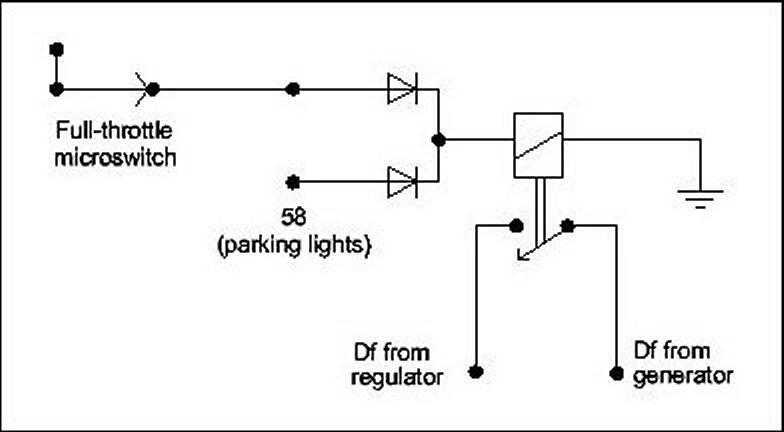
If you want to get more complicated, you'll want to make sure that your charging circuit doesn't cut out at night, otherwise the lights would go dim as they switch to the battery as a power source. The diagram shows how to achieve this, via a relay, two diodes and a connection to the parking lights.
Headlights and Starting
By Rod Young
February 1988
In 1971, VW introduced a very worthwhile feature to all their cars, one which many other makes would do well to adopt. The ignition switch was given an "X" contact which becomes live when the ignition is switched on, but which goes dead again when the key is turned to the "start" position. This terminal supplies power to certain high current-consuming accessories such as main headlights, ventilation fan, rear window demister and windscreen wipers, whereas earlier VWs and other less distinctive marques have these consumers supplied by the ignition circuit.
The advantage in this is that when you come to start the engine, the battery's full capacity is available instead of being robbed by something else being switched on. Also, the main lights switch off with the engine, so that it is much harder to get a flat battery from leaving your lights on.
What I propose here is an emulation of this marvel, without you having to go out and change your steering column complete with ignition switch. One relay can do the job, or at least most of the job, as the diagram shows only the headlights being switched.

The relay coil is energised whenever the ignition is switched on (power at 15), but current flow stops as soon as the starter is actuated (power at 50), since there is then twelve volts at both sides of the relay coil and no potential difference. The relay drops out and the headlights, if switched on, go off, but come on again as soon as you let go of the key. When you turn the engine off again, the lights go out too - easy! Only the main headlights are affected, the parking and tail lights remaining as before.
Theft-Proofing Your VW
By Rod Young
April 1988
Forget burglar alarms - nobody takes notice of them any more, and car thieves know how to disarm them. Anyway, they're a real pain when they go off in the middle of a rainy night and you're lying warm in bed. There is a much easier and cheaper way to make your VW impossible to start.
It consists of a small device that can easily be hidden in the engine compartment of any car - behind the fan housing of a Beetle, for example. All you need is a relay, a resistor, a diode and a mounting bracket.
The wires from the relay are attached to both sides of the ignition coil, one to earth and one to either the left side blinker or brake light, which are just nearby in the engine compartment, so that you don't need to run any wires through the car.
The relay you have to use has two sets of contacts. One of these effectively shorts out the distributor points while the relay is not activated. To start the engine, the relay has to be activated. This should be a procedure known only to the owner, and not something that can be worked out by any potential thief, through the use of a hidden switch, for example. I know somebody who had his car stolen in spite of a hidden switch beneath the dash that immobilised the ignition, so you can't have anything that a thief can find.
This is the new way to start your engine: turn the ignition on, either switch on the left side blinker or step on the brake pedal, depending on which way you've wired it, then turn the key to the "Start" position. Every time you start the engine, the same procedure has to be followed.
How it works:
The lower set of contacts makes a connection from the -ve of the coil to earth whenever the relay is "dead", so disabling the ignition. When the relay is activated by current sent from the blinker or brake light wiring (whichever you prefer) through the diode (a diode allows current flow only in the direction of the arrow), the relay switches on, lifting the short from the coil and allowing the ignition to work as normal. At the same time the second set of contacts switches together, sending current from the "live" ignition lead through a resistor to the relay coil, ensuring that the relay stays switched on. The resistor is used only to reduce the current flowing through the relay coil, so that it doesn't become hot.

All the components are available from electronics stores. Choose a DPDT (double pole, double throw) relay, for example a telephone relay. It is better to choose one that you can easily make a mounting bracket for. If you have a six-volt car, make sure the relay coil is a low resistance one, about 60 Ohms. Nearly any diode will do - choose a 1N 4001, and for the resistor, a 470-Ohm, 1/2 Watt. The relay is the most expensive component - about six or seven dollars. The other components are very cheap. You may choose to use a multi-pin connector to make it easier to remove the engine - these cost a bit more.
I prefer to stick to standard VW wiring colours. In this case, you should use a black wire from the coil +ve, a green wire from the coil -ve, a brown wire to earth and a black/white wire to the left blinker or a black/red to the brake light.
To make your VW absolutely theft-proof, it should also have an engine-lid lock, so that no one can tamper with your fancy wiring. A dash or console-mounted flashing light (it must be the same type as the well known car alarms) will also scare off a lot of potential thieves, perhaps saving you some break-in damages.
The best theft protection device is the one you build yourself. However, if you're not sure how to put all this together, then see me and I can do it for you.
Headlight Telltale
By Rod Young
July 1988
If you are one of those people who continually leave their lights on or their keys in the ignition, this little reminder circuit could be helpful to you.
Taking the example of the headlights first, a buzzer gets its power supply from the parking lights (58). If the door is opened, the door light switch makes contact and the buzzer goes off. This should be enough to warn you to switch the lights off before you leave the car. You will need to insert a diode in series if the buzzer is not a polarised device (it might work in reverse).
Now for the example of the key in the ignition. A special feature is found on vehicles in the USA. If the key is left in the ignition and a door opened, a buzzer goes off. This requires a special contact on the ignition switch which senses that there's a key stuck up there. Fortunately for us, this special US-spec switch is available at VW dealers; in fact it's the only available replacement for Golfs and late-model Beetles and Type 3s. This switch also has a contact which senses that the ignition is switched off, which is used for side marker lights. The terminal that we want is identified by "Su", short for the German word "Summer", or buzzer. The "Su" contact becomes the power supply for the buzzer in the diagram instead of "58".

Now, whenever you leave your headlights on, or if you leave the key in the ignition and try to leave the car, your car won't let you, or at least it will voice a vocal protest.
Update by Phil Rixon
The tech tip in the July 1988 issue explained how Golf and late-model Beetle/Type 3 owners could fit a replacement ignition switch that has a contact that senses when a key is inserted in the switch. This was the basis of a warning system that prevents the keys from being left in the ignition.
When I was fitting one of these switches to my 1976 Golf, I came up with another idea for which this switch could be used. As the contact marked "Su" becomes live whenever a key is in the switch, why not use this as the power supply for the radio cassette? This way the battery won't be drained if you forget to turn the sound off when you leave the car, and you don't need to have the ignition turned on if you are parked and want to listen to the radio. This provides the VW-vehicle with a pseudo ‘accessories’ position for its ignition switch without interfering with the key warning function.
(Good idea - I tried this some years ago, but on the switch I had, the "Su" terminal went dead a few degrees from the "off" position, even before the ignition was turned on, so that there was no way of combining current from the two with relays and having an uninterrupted power supply. It's still worth investigating, though - Rod Young)
Steering Column Update
By Rod Young
August 1988
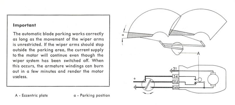
If you've got a pre-1972 VW and want to update to a late-model steering column, which is a good idea if you want to take advantage of such goodies as stalk-controlled wipers and washer, the late type ignition switch and a steering lock, you've got a problem you probably never even thought of. When the factory changed to the stalk-mounted wiper switch, in their wisdom they also changed the whole switching arrangement. You can use your old wiper motor with the new switch and get the wipers to work, but they won't switch off properly! You will have lost the in-built "dynamic braking" facility, which will cause a problem. You will probably find that the wiper arms will reach the bottom of the screen, but instead of stopping there, they will continue back up the screen for a few degrees. Depending on the supply voltage available and whether the screen is wet, they may even take off again for another sweep and just keep on going. Then the only way to stop them will be to switch the ignition off.
The problem arises because, under the old arrangement, the wiper motor receives its supply for self-parking internally, independent of the wiper switch, and is earthed through the switch for dynamic braking. This happens through the brown wire attached to the terminal marked ‘31b’. On the new type, the switch alone is involved in both self-parking and dynamic braking, and it is linked to the motor by a green wire that terminates at ‘53e’.
The obvious solution is to use a late-model wiper motor as well, but this may be impossible depending on the year of the car, and expensive. Fortunately, there is a cure, and it's very simple.
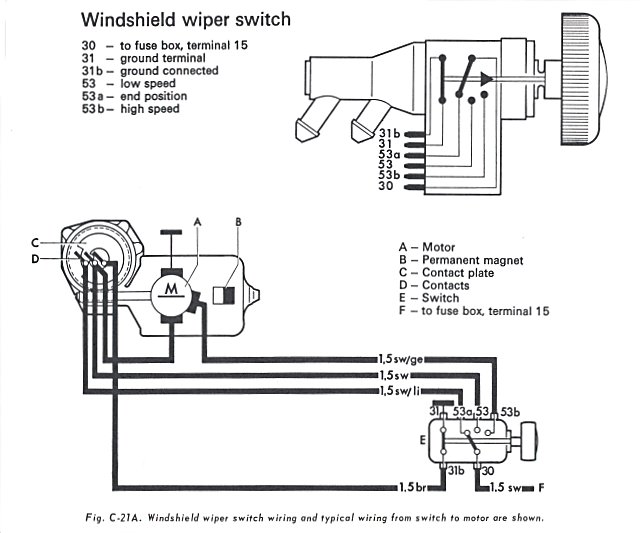
Terminal 31b on the early wiper motor is live when the wiper arms are a few degrees either side of the bottom of the screen. When the early switch is turned off, 31b is brought to earth and the motor operates as a generator into a dead short, slowing it down. (This is dynamic braking). The new switch cannot switch to earth when it turns off, so another way must be found. I've discovered that a 5-Watt 15-Ohm power resistor attached to terminal 31b of the motor on one side and to earth on the other side works beautifully to slow the motor down when it is switched off. The resistor does pass current when the wipers are on as well, but since it's only a few degrees per sweep, it doesn't get hot enough to be bothered. The above-mentioned resistor can be bought at any electronics supply store.
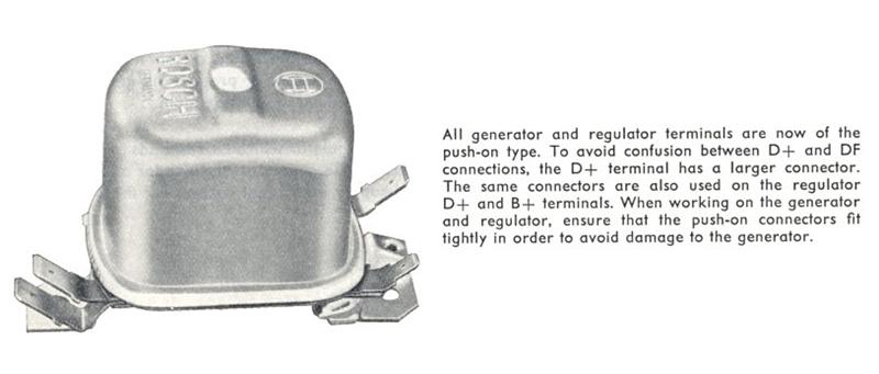
Electronic Regulator
By Rod Young
September 1988
If you have an air-cooled VW, it most likely came equipped with a generator instead of the much better alternator, used from about 1973 and on. (It is interesting that while the whole world is using alternators, Beetles currently made in Mexico are still using generators!) These generators work in conjunction with an old-fashioned electro/mechanical voltage regulator, and when yours goes bung, you won't wonder any more why Bosch is such a profitable company.
More modern vehicles are equipped with a solid-state electronic voltage regulator that works in conjunction with an alternator. These offer the advantages of no moving parts to wear out, no contacts to burn, no need to re-adjust periodically due to wear and a stable voltage output. Best of all, some of them, the locally made variety, are exceedingly cheap when compared to the OEM part.
I wanted to take advantage of all the above attributes on my generator-equipped Type 3 (I really would like an alternator-equipped Type 3, but that's damned near impossible). As well as that, I especially wanted a very smooth, stable output voltage, since I've converted this car to electronic injection, and I had heard that some strange, seemingly untraceable injection faults can be caused by a faulty regulator.
But these electronic regulators are designed for alternators, aren't they? Well, the regulator can't tell the difference where it's getting its juice from. However you can't use the same regulator as Bosch alternators use, for a reason that I am about to elaborate on.
The job of the regulator is to switch on and off the field current of either the generator or regulator, so that the output voltage is kept as near as dammit to 14V. On Bosch alternator systems, one end of the field coils is earthed inside the alternator and the regulator switches a positive current to it. On Bosch generator systems, however, the reverse is the case - the generator field coils pick up a positive supply from within the generator, and the regulator switches this current to earth. The sort of regulator you need to find, due to this fact, is one that ‘sinks’ field current, that is, switches it to earth.
After checking at an auto electrician's, I found just the item - an Ingrams 831210, priced at about $20. Don't ask me what it was originally designed to work on, though.
Now, if you know anything about regulators, you'll be aware that those designed for generators have what's called a ‘cut-out relay’ inside them. This switches in above a certain generator speed and prevents the battery from trying to turn the generator as an electric motor when the engine is not running. You cannot dispense with this feature, and the new electronic regulator does not have it, as it was designed for an alternator, after all. This means that you'll have to keep your old mechanical regulator and work it just as a relay, with its voltage regulating function taken over by the electronic box you've screwed down next to it.
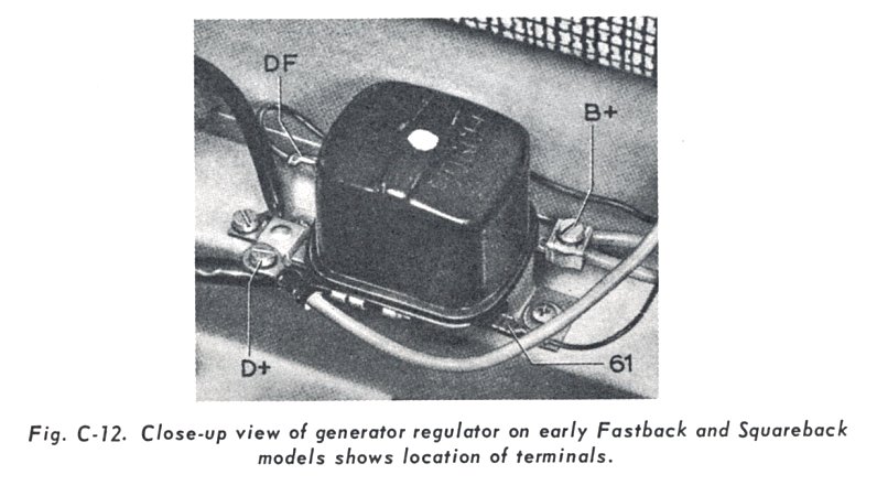
The mechanical and electrical connections are quite easy. Just find a spot next to the original regulator and screw the new one in solidly. Leave the two thick red wires (D+) attached where they are. The new regulator is earthed through its case and has two terminals - D+ and DF. Pull the green wire from the DF terminal of the old regulator and attach it to the DF terminal of the new one. Then get a piggyback spade-grip terminal and put it onto the warning light terminal of the old regulator (61). Push the old wire (blue) back on and then run another blue wire from the piggyback to the D+ terminal of the new regulator. Done! By that I mean that's all and there's nothing else to it and you've finished the job.
I lied - the output voltage might need to be adjusted. The new regulator is adjustable via a trimpot from within. Pull the top off the case and, while somebody is holding engine revs steady at about 1500, turn the trimpot with a jeweller's screwdriver until the battery voltage (measured directly at the battery) shows 14V. Do it right and it will stay there for evermore.
One of the great advantages of the new set up is that, in the event of a failure of the electronics, you still have a backup mechanical regulator and only have to swap two wires to get it going again.
PS. The above modification is for 12-volt cars only!
Why Have an Ammeter?
By Rod Young
October 1988
If you are the type who likes to imagine he's sitting in the cockpit of a 747 while driving, one of the gauges you'd probably fit into the control panel is an ammeter. VDO, the only brand of gauges that you should consider putting into a VW, makes three gauges that you could install, a 30-0-30 Ampere (part no. 190 305) and a 50-0-50 A model (190 301). The first would be suitable for a generator-equipped car and the second for a car with an alternator. These two gauges are both Australian-made, and if you want a bit of German quality, go for part no. 190 302. This one is a heavy-duty 60-0-60 job.
The aspiring Jumbo Jet pilot will probably already have a voltmeter as well, so what's the point of an ammeter? Actually, they have some worthwhile advantages. You get to see every little swing of current going on between the generator/alternator and the battery, so if the battery is not quite up to scratch, or if the regulator voltage setting is down a bit, you'll notice that you don't get the normal deflection on the gauge. You'd be lucky to pick this up on a voltmeter at all. If there is a fault anywhere in the charging system, an ammeter will go wild, whereas a voltmeter will barely flicker. The greatest difference is that an ammeter lets you know straight away that something is wrong.
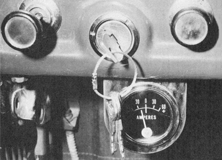
The instructions that you get in the ammeter box show that you should replace the cable link between the alternator or generator regulator with two wires which both run to the gauge. In practice, this means that on rear-engined VWs, people almost invariably run two wires from the back of the car, along the floor and up to the dashboard. One of those wires is unnecessary! The main power feed, that is, the big, thick red one which leads to the headlight switch or fusebox, is already attached to the terminal of the alternator, so you can tap off that to get to the gauge. Then run another thick red wire straight back to the battery. If two wires are used, there is a lot more resistance in the system and the charging may be affected.
This is only the first of your worries. The next thing which is not included in the fitting instructions and is therefore usually neglected is that the charging voltage which the battery finally sees will be lower after having to go through the extra resistance of those long wires and the gauge itself. You will have to carefully adjust the output voltage spring stop at the regulator while making sure that the voltage at the battery is 14 V+/- 0.2 V. If you have an alternator with an internal electronic regulator, too bad - don't fit an ammeter, because you will always have flat batteries. If you have a Bosch replacement electronic regulator, you'd better go back to the mechanical type, or an adjustable electronic one (Ingrams brand). I have one of those, and even with the voltage fully boosted up, it wasn't high enough and I had to resort to the dirty tricks department to get it up to 14 V.
Then there is the safety aspect. The wire(s) you run through the car are of the big, thick red variety and obviously can't be fused for safety. You have to be very sure that they can't chafe on bulkheads, because if there's a short, it's a very short short indeed, and only a short way to a burned-out shell.
I remember one trip I was making to the airport with a friend in his non-VW. Someone had previously wired up the ammeter to the normal standard that you always find on cars (no-one ever does good wiring, and every car looks like it has been done by the same butcher. Are there uniform standards of mediocrity?) We were about ten minutes from the airport with the plane about to take off in fifteen, and after a wrong turning, the driver had to make a sudden U-turn. In the middle of it, with approaching traffic - the engine stalled, there was no power and nothing but the acrid fumes of burning insulation. I've never seen a man move so fast in his ripping open the bonnet and undoing the battery clamps. The ammeter leads had chafed through to the firewall of the non-VW and had well and truly burned through. Needless to say, we ended up missing the plane after a quick and dirty wiring patch-up.
So, if you want to complete your jet cockpit, you’ve got to be aware of what can go wrong. Is an ammeter worth it? I’ll leave it up to you.
Electronic Idle Control
By Rod Young
June 1990
Most people, when they replace their Beetle's single Solex for twin Webers/Dellortos, Kadrons or whatever, think only of extra power. To this end they are willing to sacrifice their hearing faculties, fuel economy, drivability around town and smooth throttle operation, or just don't consider these things at all. For me these issues are just as important as the power gains, and I'm even willing to sacrifice a little power for a car that is pleasant to drive to work and back every day.
To this end, I've gone through a several-years-long seat-of-the-pants jet-changing sequence, designed a quiet air filter, engineered in balance tubes and optimised the throttle linkage. These improvements have been good for three previous Zeitschrift articles, if nothing else.
The latest improvement to drivability isn't startling, and may be difficult for most people to implement, but I like it. That's all that matters.
Let me lay the groundwork to introduce why this improvement is worthwhile.
More often than not, replacement carburettors don't have some of the niceties found on carburettors for road-going cars. Devices such as a choke, warm-up fast idle and a brass fitting for vacuum advance aren't all that necessary when you go racing.
So most people put up with a motor which has huge flat spots and stalls while cold and which doesn't take advantage of the extra fuel economy offered by vacuum advance.
The stalling especially bothered me. Without a fast-idle cam, or even linkage on a manual choke, a motor will not idle properly while cold if the idle speed is set for proper hot operation.
The other thing was vacuum advance. My Weber DCNs didn't have fittings for vacuum advance, so I hooked up the distributor diaphragm to manifold vacuum. The difference between using a source of manifold vacuum and a so-called ‘ported vacuum’ source is that at idle, no vacuum gets through from the ported vacuum fitting, ie. when the throttle is closed. This is because the butterfly plate covers the orifice when it is closed. Vacuum gets through from the manifold at all times.
Using manifold vacuum works OK for part-throttle economy, but has a curious undesirable feature: the idle speed can become unstable, because the extra advance fed in by the vacuum advance alters the idle speed. It's a fairly well known fact that advancing the timing speeds up the idle and retarding it slows it down. This is the effect taking place. So at idle, if some small effect acts to slow down the speed, the vacuum drops as well, which further slows down the idle - a vicious circle, instead of a self-correcting feedback loop. The overall effect is that stalling is more likely.
So, summarising, what I was looking for was a system that allowed the motor to idle while cold and which allowed vacuum advance as the factory designed it.
The principle of my device is a vacuum solenoid valve, which actuates the distributor advance diaphragm at normal operating temperatures and while the throttle is open.

A wire from the coil positive powers the solenoid valve, which switches through either the oil-temperature snitch (oil cold) or the closed-throttle switch (throttle open). The diodes prevent current from flowing in an undesirable direction (the throttle switch would turn on the warning light). When the solenoid valve is actuated, vacuum is switched from the manifold to the vacuum advance diaphragm, giving a faster idle speed.
The parts needed were the above-mentioned solenoid, which is a ‘3-way vacuum solenoid’ from a series 1 Audi 100; a temperature switch from a 1976 Passat (this one is closed below 60 degrees C and was on my car already, hooked up to an oil line to indicate low oil temperature) and a small microswitch. Notice that I try to use VW/Audi parts wherever possible; I could have used a microswitch pirated from a power roof motor of a series 3 Audi 100, and nearly did, but then found an ex-Dick Smith one that did the job better because the lever was made from metal and could be bent for adjustment.
The hardest thing was to make a bracket for the microswitch so that it would be actuated just as the throttle closes. Mounting the solenoid was easy - it fitted on to the screw that holds the thermostat flaps in at the base of the fan housing. Looks just right. I then had to make vacuum hookups with VW plastic tube and VW vacuum hose, then made a mini-harness with VW wire and sheathed it in plastic tubing, just like VW does. Someone, I hope, in a few years time, is going to find this on my car and wonder what sort of weird factory accessory it was.
I thought of the idea yesterday afternoon and carried it out on the spot. Worked like a charm going to work this morning and back again this afternoon - cold idle is about 800/min, which increases to around 1100/min after about ten minutes' driving and then drops back to 800/min again when the thermo-switch and vacuum valve cut in, which is where it stays as long as I drive.
True Volts
By Rod Young
August 1990
You’ve possibly read my previous ravings about an ammeter being a nice accessory to have, but impractical, especially for a rear-engined car.
A voltmeter, on the other hand, is not only moderately useful, but also safe and easy to install. As previously discussed, is there is a problem with the vehicle’s charging circuit, a voltmeter will show the anomaly, but only a small difference in the deflection of the needle from the normal state will be evident.
For the generator/alternator to adequately keep the battery topped up without overflowing acid all over your floor, the voltage regulator should be set (if this can be done) to between 13.8 and 14.2 Volts. Let’s say a nominal 14 Volts. This voltage should be measured at the battery terminals – that’s where auto electricians stick their probes.
Accessory voltmeters, on the other hand, have their power terminal hooked up to an ignition source, usually to whatever is handy behind the dash. If this were not the case, and a permanently live source were used, there would be a constant drain on the battery through the gauge, which after all is meant to alert you to problems, not cause them.
But the ignition source is far from ideal. Due to a combination of inevitable resistance in the supply line and the ignition switch, and the effects of any consumers such as blinker, brake, ignition and so on which get their power from near where the voltmeter does, the voltmeter will give a lower than actual battery reading. The effect is most evident when the blinkers are turned on – the voltmeter might swing from 10.5 to 12 Volts alternately, whereas at the battery there may be little difference.
What is needed is a combination of a direct supply from the battery, and ignition control, so that the gauge is switched off with the ignition key. A relay will do this job properly.
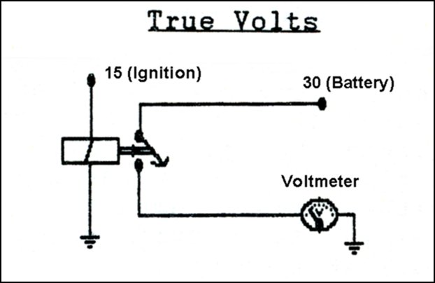
Hooking up is a bit harder than the normal installation, as it’s necessary to run a dedicated wire back to the battery and mount an additional component in the form of a relay. The relay can be put near the battery or near the gauge, wherever is more convenient.
I have installed a relay in this way to a friend’s car, and he was pleased with the results. At least this way, there’s no guessing about what’s really going on.
VW’s New Modular Wiring System
By Rod Young
August 1990
The press release kit for the new Passat is more like a book than a brochure; there is so much of it. One of the things that really stood out for me, because I have an interest in such things, is the advances made in the new Passat in the area of its electrical system.
The new B3 Volkswagen Passat features state-of-the-art electronics, and a clean-sheet approach to installing and maintaining electrical components.

After an in-depth, in-service study of where existing cars suffered electrical faults, and the time and methods used to track down these faults, Volkswagen’s engineers discovered that the most common place for an electrical fault was at connection points. The reason that faultfinding took so long was because vehicle technicians had to work through an entire wiring loom to discover where the fault was located.
To tackle both of these problems, Volkswagen engineers decided to abandon the traditional wiring loom, which resembles a domestic wiring system in which a whole range of sockets, or in the case of a car, components, share the same electrical loom, despite a wide variance in electrical consumption needs. Instead, Volkswagen has opted for a system owing more to a computer, in which individual components or small groups of components, have their own separate wiring system.
In practice this means that where the B2 (second generation) Passat had seven separate electrical looms, each supplying 20 to 26 different electrical components, the latest Passat possesses 26 different wiring looms, each controlling just six or eight components.
Because of this ‘modularisation’, a technician merely has to check a maximum of eight connections to track down a fault in a wiring loom, compared to 26 in the old car. To ensure that these connections are more reliable, Volkswagen has used an ‘error-free’ type of connector, as used in computer systems, that ensures accurate transmission of data, let alone the much more simple transmission of power.
All wiring looms are not only colour-coded in the traditional fashion, but also a coded message is printed on one side, indicating exactly what the loom controls. In the same manner, every electrical connection indicates to which loom it belongs, and what it is controlling.
All these wiring looms run into and out of a newly designed fuse box and relay plate, in which solid-state electronics have replaced traditional wiring and relays. Unlike traditional fuse boxes and relay plates, the new Passat system has been designed so that the whole box can be detached from the car and checked separately, thus speeding faultfinding and repair.
In designing this new type of electrical system, Volkswagen took into account the varying needs of Passat owners, and for this reason plenty of spare capacity has been built into the system so that accessories may be easily attached to the system. In all, there is space for 200 connections from the central fuse/relay box.
The decision was also made to retain the standard 12-Volt electrical system, and not use a micro-voltage switching system used by some manufacturers, so that all 12-volt accessories could be used in the new Passat without any modifications.
I’m fairly drooling to see this sort of equipment in the flesh. Volkswagen already has some of the most advanced electrical systems of any car manufacturer, but then made the Passat’s a whole lot better. I’ve seen a picture of the new fuse/relay box, and it looks incredible.
It’s at this level of design where Volkswagens, and probably all German cars, are different from other cars. When working with VW electrical systems, you can just about get inside the designer’s head, know what was going on and appreciate that these bits were designed to be worked on (by someone with knowledge and logic facilities, that is). On other cars, the only feeling you get is that the electrics were designed for cheapness and ease of assembly, and what happens after that is the owner’s problem.
The old VW wiring looms were superbly designed, but I’ve seen some crook things done to them by people who knew nothing and cared even less. On the new Passat, I hope it will be harder for these people to do their worst.
Beetle Regulators
By R.N. Caffin
March 1991
Ever wondered just what the regulator on a Beetle generator really does? We all know it is meant to ‘regulate’ the charging supply to the battery, but exactly how does it do it, and what adjustments can you make to keep it doing the right thing? This will be particularly of interest to owners of 6V systems: we wage a continuous battle trying to get enough volts to the lights. There are one or two folklore rules of what to do, but these can actually make life worse while appearing to help. The truth seems to be a bit more complicated.
This all started when I swapped a dying battery (only five years old) out of my wife's 1960 Beetle for the nearly new one (only three years old) in my 1958 Beetle, to keep her on the road safely while I replaced the dead one in my Beetle. This presumed that I could get to the battery shop without stalling on the way, of course. Well, I got there, but the new battery seemed to die over the next couple of days, and I hadn't done anything to the system. A check at the battery shop showed the battery to be OK, so I went home to adjust the regulator (again), tighten the fan belt and charge the battery. This didn't work. The battery shop went so far as to swap the battery for a new one, even though they were sure it was OK. Still no joy. If I drove to work in the morning without the headlights the battery was OK, but driving home with the headlights on meant I could not start the car the next morning. For a Beetle owner of twenty-three years standing, failure to start was heresy.
I had been told that the way to adjust the regulator to give the ‘correct’ voltage was to tweak the spring tab at the top left of the front coil. No matter what I did, I seemed to get massive overvoltage at high speed without lights (over 8.2V) or a dying undervoltage with the low beam on (5.9V and falling). High beam was just a disaster. The simple diagnosis was a dead generator, but this was not acceptable. My conclusion was that the regulator itself was not working properly. I found that it is a far more cunning little contraption than it looks, and thought others might be interested. Please note that the information given carries no guarantees: anyone using it does so entirely at his/her own risk.
First of all, understand that the output voltage from a generator with a constant field is proportional to speed of rotation. Without any other help it would swing terribly as the car goes from idle to full revs. The regulator attempts to reduce this swing by varying the field strength.
This is my understanding of the regulator. The back coil (D) (nearest the fan housing) decides when the generator voltage is high enough to warrant connecting the generator to the battery through contacts (E). Without this, the battery would quickly discharge back through the generator when the engine is off. This bit is simple and generally does not give a problem. The front coil (A) senses the generator voltage and attempts to control it by varying the generator field strength, or the current through the generator field coil (F). This magnetic field strength is due to a large field coil around a soft iron core (no permanent magnet as far as I know). How this control is done is the tricky bit.
The current through the front coil (A) creates a magnetic field, which pulls the armature (flap on spring) down, moving the front contact arm (FC) from the left tab (L) to the right tab (R). When the generator voltage is low the flap is not pulled down, and the front contact shorts the 4-ohm power resistor (R) under the regulator to the chassis (0-V) and puts the full battery vol¬tage across the field coil (F). This is state 1. This creates a large field strength and hence gives lots of generator output to charge the battery. At an intermediate coil voltage the flap is pulled down a bit and the contact arm is between the front tabs (L) and (R), and is not touching either. This is state 2. The 4-ohm resistor (R) is now in series with the field coil (F), reducing the field strength and hence the generator out¬put. When the voltage gets even higher, because the motor is going very fast or the battery is fully charged, the coil pulls the flap right down and the front contact arm touches the right tab (R), shorting the generator field coil to the 6V rail and reducing the field to zero (and making the 4-ohm resistor hot). This is state 3. So the first stage of the analysis has the generator field (and output) in one of three states: full (1), half (2) or zero (3). This is not enough to look after a battery.
In practice the contact arm is never stationary: it seems to spend all its life chattering on one side or the other. With most relays this would be a disaster, but in this case it is actually the correct mode of operation. By alternating rapidly between full power and half power (or half power and zero power), the field effectively ends up at about the right strength to make the generator charge the battery to the right voltage. Whether the field winding (inductance) smooths out the field current or the battery is charged with a series of pulses is ‘left as an exercise for the reader’ (meaning I don't know).
The ‘simple solution’ to a lack of charging is to increase the spring tension by tweaking the tab at the top, thereby making the coil need more voltage before it cuts down the field. This seems to work, but is wrong! Done once or twice it may work, but beyond this it will start to damage your battery and eventually just not work. Done too often it will also weaken the little tab: the steel is very brittle, and eventually the tab will just fall off. If this happens you have two choices: get a new regulator or rebuild the one you have.
The reason that adjusting the tab is wrong is that the operation of the regulator is critically dependant on the spacing between the top of the coil core and the moving flap. Increasing the gap by raising the spring tension reduces the ability of the magnetic field to move the flap and the contacts. The sensitivity of the regulator is decreased.
The voltage swing required to move the contact arm the necessary distance gets bigger. Eventually you find that the voltage swing needed to go from state 1 to state 3 becomes far too large for comfort, 5.5V to 8.5V in my case. Reducing the gap will increase the sensitivity to the required level - but will reduce the output voltage too. Nonetheless, getting the right sensitivity has to be the first step.
How do you get the right sensitivity? I tried making the front gap about the same as the back gap: the flap just a little bit more open than strictly parallel. This seemed to be a good starting point, even though the output was now far too low. For the rest of this article I am going to assume that you have a simple digital voltmeter measuring between the output lug 51 (the one with big wires going to the battery) and the chassis (the mounting bracket under the regulator. A moving-coil meter will probably suffice if necessary.
What is the right sensitivity anyhow? If the sensitivity in the above state is good, is more sensitivity better? Well, the greater the sensitivity, the tighter the regulation, and the less chance you have of upsetting the battery by over-voltage. However, beyond a certain point it doesn't matter, and beyond that the whole system would appear to become unstable and cease working. The above set-point worked for me and matched other cars.
If the top spring tab sets the sensitivity, how do you set the voltage? You have to adjust the fixed tabs (L) and (R) themselves, so they are in the right position relative to the moving front contact (FC). I suspect that the fixed tabs creep in time, which is how the settings drift wrong in the first place. Adjusting the tabs is not easy: the metal is thick and there are large sparks for the incautious. I did a lot of it with the engine off (which opens the rear coil contact and disconnects the battery). You have to open the gap by moving the right hand tab back a bit, then bend the left hand one till the transition from state 1 to 2 is about right. I set this to about 6.5V as the engine came up from idle. That is, the field coil was at full strength up to 6.5V, after which the contact started chattering. Then I adjusted the right hand tab so that the output did not exceed 7.3V with the engine near to flat out and no lights. It got noisy there for a bit. The ideal charging potential for a battery under no load is, I am told, about 7.2V Don't expect absolute perfection, by the way: it isn't necessary.
After I got this all set up about right, I tried tweaking the tab down a very small amount to reduce the range of voltage from state 1 to 3: I did NOT use it to set the voltage. Gentle taps on the front tabs did some fine-tuning of the voltages. The regulator now works properly.
You will notice that there is a single-layer coil of very heavy copper wire around the rear coil. I believe that this is a safety feature. If the wiring in the car is shorted out, a very high current will result, which could be quite destructive. The current through this coil will, I believe, cancel some of the magnetic field in the rear coil such that its contacts open. This will very quickly cancel a potentially disastrous situation. On the other hand, I could be quite wrong and this could be a boost coil, designed to keep the contacts closed when the battery is almost flat and the generator is pumping a very heavy charging current into the battery. If anyone knows for sure, let us know?
If you look very closely, you will notice that one lead of the above coil of heavy wire is half wrapped around the front coil. This bit I do understand: it is a boost coil (OK, half a turn) designed to push the regulator voltage up a bit while the generator is pouring out heavy current. This is for when you have all the lights on, plus the wipers, and you have just started the car on a cold night with a drained battery. The high current out of the generator will cause extra voltage drop (sad on a 6V system), so those cunning designers have arranged for the set-point to rise a bit to compensate.
How can you tell if the problem is lack of sensitivity rather than a failing generator? It's quite easy, really. Put the headlights on full beam and set the car on medium to high revs by leaning on the choke or the throttle, and check that the contacts are at least partly chattering or sparking a bit. If the moving arm stays stuck on the left side even at high revs (and the output voltage is low as well), you definitely have a problem. Then delicately push the flap left, to short out the resistor. You should hear the engine revs drop a bit and see the generator output rocket up to well over 7.0V despite the load of the headlights. What this means, if it happens, is that the generator can give all the power needed if the field strength is correctly set. If you are too enthusiastic with this test it will probably also mean that you now have to replace both headlight globes. If you can't get a big increase it may mean that the commutator is dirty and/or the brushes are worn or dirty. A generator overhaul is then in order: this is a different story.
A final point: how does the generator get started? I have assumed that there is no permanent magnet in the field. Well, I suspect that there may be some remnant magnetic field in the field core for a start. But if you look at the charging light you will see a sneaky field current path through it when the ignition switch is turned on. Not a large current, but enough to get the generator started, after which it can bootstrap itself up.
I mentioned above that you could rebuild the regulator if it is damaged. This is possible without too much hassle: a good drill press and some small taps are all the special tools you need. I had broken the support tab at the top and had to replace it: I put a setscrew in while so doing. I may also put in adjustments on the front contacts if I ever have time.
Of course, if one of the springs on the flap is damaged, you may have to be bolder. You can remove the whole regulator, drill out the various rivets, and disassemble the entire mechanism if you want to. Then you get another wrecked regulator and swap parts. Finally, you bolt it together again (rather than trying to rivet: messy). Just make sure you don't break any wires, don't have bolts sticking out where they shouldn't, and get the bits lined up square.
Finally, if one of the contacts has burnt out, you can replace it with the spring arm and silver button off a high-power relay. This requires disassembly as above. Try to pick a relay rated for heavy DC use if you can: the button is generally made of a hard¬er material on these. A headlight relay is excellent.
A Broad Look At Fuseboxes
By Rod Young
July 1991
I've had reason lately to do a bit of work on fuseboxes from a variety of VWs, which has made me happy, as it forms the basis of a nice little article.
I’ll take things in the order of models worked on.
The first job involved an engine compartment fusebox from a 1952 split-window Beetle. Oval windows have the same sort of thing. Four of the little screws that hold the wires into the fuse blocks had seized, and no amount of WD-40 and coaxing with the right screwdriver would get those little mothers out.
Quite conscious of the fact that if I wrecked this thing, a replacement would be hard to come by, I bit the bullet and attacked it with the power tools. The screws are only 4 mm diameter, so a steady hand was required. First I ground them flat with the brass block and drilled a 2-mm hole through the middle of each screw. I tried an EAZY-OUT in each one, but the solution wasn't to be quite so easy. So I had to drill and tap. The right pilot drill for a 4-mm thread is 3.25 mm. I had a 3.2 - near enough. All the holes I drilled were slightly off centre, which left a sliver of the steel adjusting screw inside a brass hole. No problem, really, as the tap cut through rather nicely, leaving a part-brass and part steel thread.
Then I had to remake the little screws. I never throw away any serviceable metric fastener, and so found a couple of taillight screws, which had the little protrusion at the end. I cut them to the right length and cut a screwdriver slot into the top with a hacksaw. Worked like a charm!
Next in years was a 1964 Beetle. Well, I did this job a few years ago, but for the purposes of this story, what does it matter?
Those fuses, like all Beetle ones made since, have brass male terminals pressed into Bakelite or plastic. The terminals that hold the fuses in place are pressed in, together with the terminals that accept the wires. You'd think they would be spot-welded together or soldered, or something, but they're just pressed in side by side.
This particular fusebox had a continuity problem, which was traced down to a break between two of these brass terminals, in spite of the fact that they touch each other over a fairly large area. No chance of removing the terminals from the fusebox, so I had to clean up the area where they came together and thoroughly solder. Problem solved, and I've never come across the problem anywhere else since.
Next fusebox was on a 1980 Golf. This one had two separate faults - the thermo fan wasn't switching on and had been badly bypassed; and the blinkers sometimes didn’t work, but the windscreen wipers gave a sweep periodically instead!
The Golf 1 fusebox is something of a flawed masterpiece. Instead of separate wires pushed onto large brass terminals that you can see, you have a number of coloured multi-pin plugs which push on, hiding the contact point. The separate plugs satellite out to different corners of the car, so that when you pull a harness out, it detaches easily from the fusebox and goes back on again with no more than a press - great. But to get that ease of disassembly, they designed in a microcosm of crossed paths on a printed circuit board inside the fusebox, which is also a relay board. In German it is descriptively called the ‘Zentralelektrik’.
You can pull it apart so far, but then you meet an array of soldered brass rivets, so that's where you stop unless you're very keen. You never see the printed circuit board proper, so you either buy a new Zentralelektrik ($$$) or bypass. And to bypass neatly, you have to know what’s going on.
In the case of this Golf, the break in connection in the fan circuit was deep inside the fusebox, but all it goes in there for is to communicate with a fuse. I used one of those big black fuse holders from the reversing lights of a late Beetle. They're excellent, as they have a male terminal at each end. I put it where it could be accessed for fuse changes.
The other problem was due to an intermittent lack of an earth supply to the blinker relay. If you hit a bump, it went away. Trouble was, the circuitry in the windscreen wiper intermittent relay is fairly sensitive and easily triggered by spikes in the power supply, hence a single sweep of the wipers every now and then.
The problem was too deep inside the fusebox, so I had to clip on a proper VW auxiliary relay holder to the side of the fusebox and plumb the blinker relay wires, with a decent earth, into that.
It's fairly common for the main earth to Golf fuseboxes to fail altogether, and once again, it can’t be got at. Golf 2s got a new fusebox, and I hope they fixed these problems.
Next problem was a 1982 Audi 5+5. Same fusebox as the Golf, but extensively jury-rigged to make everything work. The problem here was that the output pin on the fuel pump relay (injected, don't forget) had got hot, melted the plug and the fusebox and the car stopped. Very embarrassing. All early Golf GTIs had the same problem. The Audi owner had replaced the fusebox twice and asked me to fix it so the problem wouldn't recur. I hung a relay on the side to reduce the current going through the pin on the fuel pump relay, but there's also a factory fix: the pump relay is hung onto the side of the fusebox and wired to a plug which picks up all the terminals from the relay board, bar the output pin. This comes directly from the base of the relay, where it can’t hurt anything if it ever gets hot. Golf 2 fuseboxes have massive pins on the power terminals - problem solved. By the way, you need special tools ($$$, and hard to get) to remove the terminals on any of these fuseboxes, so it s not for just anybody to fix.
Last in chronological order is the new Passat. They've completely redesigned it, as before described in Zeitschrift, and I’d like very much to get to work with one. Though if they're that well designed, I should never have to!
Glen's Wiring Tricks
By Glen Jensen
October 1992
Kill Switch
One of the easy ways to put in a kill switch is to short the negative side of the coil (terminal 1) to chassis ground, through a concealed switch. This works well as long as you don't leave the ignition switch on for any length of time with the kill switch activated. The coil works hard enough as it is, and could burn out if this occurs. If you wire a capacitor in line with the cable going to ground, this will not happen as easily. A high capacitance, low voltage capacitor will work. Part R-4015 in the Dick Smith Catalogue should work well.
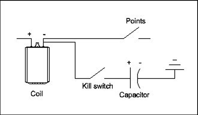
High-tech Kill Switch
On my fuel-injected Transporter I use a simple relay circuit to automatically kill the fuel pump when the ignition is turned off. To start the bus, turn the key to the run position and push the switch. The output to the pump will hold the relay on until the key is turned off, thus arming itself again. This has a simple advantage. Kill switches only work if they are turned on, but this one does it for you. Use a high contact rated relay (30 amps) and solder your connectors if possible as crimps can loosen over time. If you use a double pole relay you could use the second set of contactors to light a warning lamp on the dash.
Showing Your Colours
By Rod Young
December 1993
There is definite common sense, even a certain purity in the colour codes used by Volkswagen and Audi for their wiring. Other manufacturers have their own codes, unlike any other makers’, which may also differ from model to model within the same model, and even on the same car. I once came across a wire in a Japanese car that changed colour three times as it went through connectors. VW/Audi colours have been the same for the basic functions since the 1940s, and also match those of other German manufacturers to a certain extent.
Starting at the source of power, the battery: a permanently live source, i.e. a ‘hot’ wire, is red in colour. This is somewhat of an international, but by no means universal, standard. The connection between ‘red’ and ‘hot’ are obvious.
You must have noticed that any wire attached to the car's chassis, to ‘earth’, is brown in colour. Another natural connection - earth is, after all, brown.
High-beam headlights are bright in colour; therefore, logically, the wires leading to them should be white.
Low-beam is less bright, a little dimmer, yellow to be precise. Parking lights are only a shade of their big brothers, hence the grey wires providing current.
There is no obvious colour for wiring associated with the ignition circuit. VW/Audi uses black, with an assortment of traces to distinguish various consumers of current. More about traces later.
Any warning light wire has blue as its basic colour. Pure blue feeds the warning light virtually every car has - the charge warning light. Others are blue with various traces.
Green with its associated traces has, since the advent of water-cooled VWs, become associated with all to do with windscreen wipers.
A trace on a wire used to mean in the Beetle days that the wire had been through a switch of some kind. Therefore red/black goes to the starter solenoid. But somewhere along the line it also came to mean an un-switched supply to a particular consumer. For example, on Golfs a red wire with a grey trace, permanently live, goes to the cigarette lighter. Some designer obviously had a sense of humour here, as grey is the colour of cigarette ash.
Black/red goes to the brake lights (because of red lenses?). Black/blue is for reversing lights. Black/yellow comes from the so-called ‘X’ contact - the one that makes the headlights go out when you start the engine. Black/white goes to the left blinkers, black/green to the right. So logically, which colours are used for the wire between the blinker relay and the blinker switch before the current is split up to either side? Black/white/green, of course, the only wire on any VW/Audi with two differently coloured traces.
Brown with a trace means that there is a switch to earth. So the wire between the interior light and the door switch, which is earthed, is brown with a white trace (white signifying light).
How do you tell the wires leading to the right-side high and low-beam headlights? They both have a black trace.
Grey, basically for parking lights, has a variety of colourful traces. Grey/black is for the left side parkers and tail-lights; grey/red for the right side; grey/blue is generally for dash lights; grey/green for the number plate light on cars with the split parking-light system (one side parker/tail-light on with the blinker arm); grey/white for the feed to the fog lights (fog is white, you know); and grey/yellow for the rear fog lights (not as bright as front fog-lights).
Blue/green on Beetles means the oil pressure warning light. Of course, early Beetles had a green oil warning light! Newer cars now have blue/black. Blue/white is the high beam waring light - white for the high-beam, naturally. Blue/red means the blinker warning light. Blue/brown is for the brake/handbrake warning light.
Pure green was used on early Beetles for the supply to the wipers, and on later models for the self-parking facility. Golfs took this a few steps further. Green/black and green/yellow also go to the wiper motor; green/red to the windscreen-washer pump and green/white to any rear washer pump.
With the increase in equipment being added to modern cars - air conditioning, cruise control, fuel injection etc., the consistency of colours was inevitably lost in duplication and a whole lot of apparently illogical colour choices. So yellow is now used for the dynamic oil pressure warning system as well as for low beam. The fuel gauge sender now has a violet/black wire (OK, so the Beetle's brown was illogical too.)
But, I ask you, what other cars have such evidence of natural, human influences shining through in a feature as mundane as their wires? Another reason why VWs and Audis are special, I think.
Reception Problems with Car Radios
By Bob Reiter
March 1995
Many reception problems with car radios can be linked to the antenna. To check the antenna, use a multimeter to measure the resistance. It should be open circuit between the mast and the chassis of the car. The resistance between the top and the bottom of the mast should be in the order of 0 - 20 Ohms. Ensure that the mast is fully extended and is clean. If anything measures incorrectly, there is a fault in the cable or the antenna. Also there should be no continuity between the mast and the centre pin of the cable as there is a capacitor in line. The best way to troubleshoot the antenna and cable is to use a spare antenna and plug this directly into the radio and hold it out the window. A cheap car antenna can be used for this test.
If the car is fitted with a window antenna, reception will not be as good as with a normal telescopic antenna and is more susceptible to interference. This is because the signal is partly obstructed by the body of the car.
When installing the car radio into the car, the antenna trimmer should be adjusted on the radio if it has one. Tune the radio to a weak station around 1200kHz to 1600kHz on the AM band and turn the trimmer until maximum signal can be heard. If the trimmer has no effect despite the antenna and cable being 100%, there may be a fault within the radio.
FM reception can be limited to distances of 50 – 100 km depending on the terrain. The signal effectively travels in a straight line, and hills and tall buildings can effect reception. AM signals travel much further, but because of the nature of how AM transmission works, it is more susceptible to interference. Interference is caused by many things, including power lines, electrical machinery, and even lightning. The car can also cause interference from a faulty alternator and other electrical devices. Radios equipped with AM stereo are even more prone to interference. To reduce bandwidth of the AM station and hence reduce the interference, the radio will automatically switch to mono when the signal becomes too weak. This also occurs with FM stereo.
Light Improvements
By Lance Plahn
February 1997
Over the years headlights on Volkswagen have come under a lot of criticism. Volkswagen did little to improve the situation, by continuing to fit 40/45 watt bulbs.
There are a number of improvements that can be made, one of the most popular being to fit halogen bulbs which come in an array of sizes, ranging from 55/65 to 90/130 watt. Of course if the reflector is in poor condition, there will be little gain. Good second hand reflectors are hard to find and new ones are expensive. So if you own a 12-volt Beetle, Kombi or a Type 3 with poor lights and you're looking for a cheap and practical way to improve the lights, you may be interested in installing seven inch sealed or semi-sealed beams to which headlight protectors can be fitted.
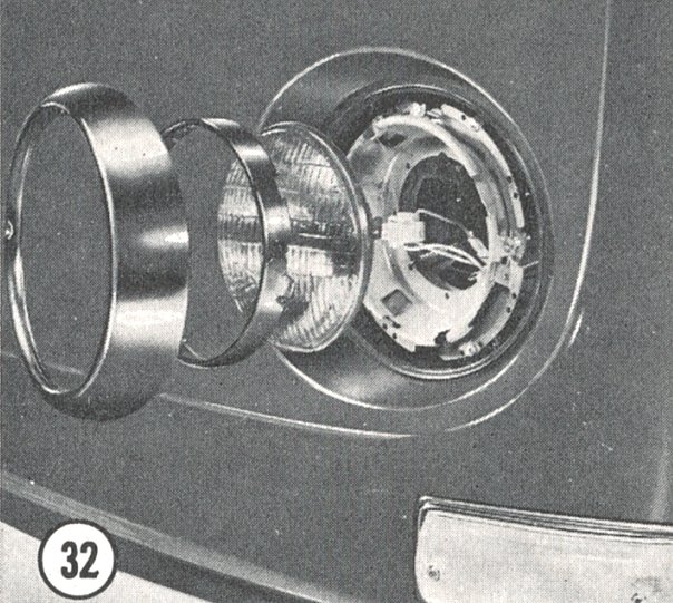
First obtain a pair of lights (including beams and bases) from a Holden or Ford from the seventies. Before removing your old lights it may pay to mark on the garage wall the position of high and low beams for reference. Now remove the old units and temporally install a light connecting the wiring and position it so it shines on the reference marks previously made on the garage wall; this will give you an idea where the light has to be positioned
Other points to watch are to keep the light central of the outside chrome rim, and not to have the light too far forward or back in relation to the outside chrome rim. As you can see it will take a little time to work out where to position the light so the lights can be focussed and also look neat. Having done this, you will have to make at least three brackets to hold the light base securely in position. The brackets can be either welded or bolted to the light recess, but the base should be bolted to the bracket for service reasons.
Some thought should be given on how to install park lights. If you install semi-sealed beams these units usually have a small hole in the reflector with a rubber grommet into which a bulb and holder is fitted. To fit sealed beams you have to obtain units which have a small clear section in the reflector then attach the park light to the light base. Some of the later Holden in-the seventies had this set up.
Now all that remains is to fit the headlight rims. You may have to trim the adjusting screws to fit the rim, or fit rims from a ‘seventy-five or later Kombi which do not have adjusting screws in the rim, for a cleaner look.
From 6 Volts to 12 Volts
By Lance Plahn
July 1997
I know it's an old story, but with the revived enthusiasm in VWs along with greater numbers of cars changing hands, more and more people are asking what a 12-volt conversion involves. What is about to be suggested here is that you may not need to rush into a higher-voltage system to get the results you're after. Let's first look at why you are unhappy with the 6-volt system, which was fitted to all VWs sold Australia prior to 1968.
Without a doubt, hard starting followed by poor lights, are the two main criticisms of elderly 6-volt VWs, followed by the fact you can't install a 12-volt radio/cassette system. There are other grounds for 6-volt discontent, but theses are the main ones. So, before we consider going to the considerable expense of a step-up in voltage, let us look at some ways of overcoming these problems.
Voltage drop, for a start, is the worst enemy of the 6-volt system. A loss of one or two volts can have devastating effects. Making sure all connections, including fuses and earths, are clean, tight, and corrosion-free is a good first step. A CRC aerosol product called Electra Clean is handy for this job. Next step, presuming you're having starting problems, is to try installing a relay on the starter motor. Ensuring a good earth at the starter motor is also important. You do this by installing a longer bolt on the earths strap at the floor pan end, then running a lead-with an eye at each end to the lower starter bolt.
To get a better charge at the coil, a little attention to the wiring can also help. Power from the battery arrives at the headlight switch via starter motor and voltage regulator, and then proceeds to the fuse box back to the ignition switch. Running a wire from the headlight switch to the ignition switch shortens the route and reduces the number of connections, thus improving voltage supply to the coil.
For the lights, relays fitted to high and low beams will improve brightness noticeably, as will higher-wattage halogen globes. It's also important but neglected by many VW owners endeavouring to improve their lights to ensure both your lenses and reflectors are in the best-possible condition. Re-silvering is not an expensive business and should be considered. Many VW parts suppliers can supply the popular Rossi headlight conversions, which accept a seven-inch sealed or semi-sealed assembly.
Where your 12-volt cassette/radio is concerned, you'll find that 6-volt-to-12-volt inverters are easily found in places like electronic shops.
There is also another approach: that of fitting an 8-volt battery. This was popular back in the 1960s and 1970s, but is less so today as these batteries are hard to find.
Now, let’s assume you've tried all this, or at least considered it, but still want to convert to 12-volts. What do you need to think about?
The wiring of your 6-volt car should be generally okay when it comes to handling the extra voltage, as wires are graded according to current, not voltage. 6-volt cars actually have bigger wires as they were designed for more current. You would only have to check for corrosion, loose ends and any damage to the insulation and your existing wiring will be fine.
Early 12-volt Beetles were fitted with a 30-amp generator, while later models had a 50-amp alternator with external voltage regulator. Upright 1600 12-volt Kombis had a 38-amp generator. Any one of these units will fit a 6-volt VW, but you will need a new generator stand, backing plates, strap, 12-volt pulley and 12-volt regulator if there's no inbuilt regulator. Most VW shops sell an alternator conversion kit that provides all this, along with an 51-amp Motoroa alternator containing an in-built regulator.
Changing over a generator takes about one hour if you've got a good workshop manual to help you along your way.
What is not really recommended is the fitting of a non-VW alternator. This generally requires a lot of fabrication, making up retaining and adjusting brackets. The foreign alternator is often flimsy and always in need of repair, fouls the boot lid, and often seems to get in the way when working on exhausts, spark plugs, or filling with oil. Another major problem is belt contact on the pulley. If there's not enough of this, there will be some slippage, which can be harmful as the same pulley drives the fan. Remember, use original VW parts whenever possible.
Next step is to fit a 12-volt coil, available from manufacturers such as Bosch. You could buy a brand new one, but old coils rarely fail and a cheap used one from a VW wrecker will probably be fine.
After you've installed your generator/alternator and coil, it's time to replace the battery with a 12-volt unit. Most important is the method of retaining the new battery, which will be larger than the original. Loose batteries flopping around under VW rear seats have been known to short out and start fires. Don't even consider tempting fate by leaving the battery loose. Use a standard VW battery retaining strap from a 12-volt Beetle, and a standard VW insulating battery cover. The seat must not touch the battery terminals when everything is together.
Then, all globes in the car must be replaced by 12-volt globes. Starting from the front of the car, replace all globes for: head and parking lights, indicators, warning and instrumental lights in speedo and fuel gauge, interior light, rear stop/ tail/indicator lights, and number plate light. A 12-volt horn, and indicator light relay, must also be fitted. Fuses, and condenser in the distributor will handle the extra voltage and do not require changing. Also, the fuel gauge will continue to work on 12 volt, although fitting a 56 Ohm, one watt resistor in the power wire will help it last longer.
Running 12 volts through a six volt wiper motor has its effects too, the wipers operate so fast that the blades hardly touch the screen, causing the excessive wear in the linkages. There's also often a problem switching the wipers off. The best options here is to use a 12-volt wiper motor from a later-model Beetle. You'll have to fit the new motor to the old assembly, which might need some minor modification, but you’ll also have the advantage of a second speed if you also use the later 12-volt switch.
The six volt starter will turn twice as fast on 12 volts, but the service life won't generally be greatly affected - although it will tend to chew away the ring gear over a period of time. Naturally problems like this can be overcome by fitting a 12-volt starter. Then you'll need a 6-to-12 volt conversion starter bush (fitted in the gearbox bellhousing), which a VW parts shop can supply. Alternatively, use a 12-volt starter off a semi-auto Beetle, which doesn’t have a rear starter bush. Using any 12-volt VW starter also means changing the engine flywheel, as the teeth spacing is different from a 6-volt starter/flywheel.
Actually, a 12-volt flywheel can turn out to be a major job because you'll need to ensure the new one has the same clutch size as your engine, if you want to avoid the cost of a new clutch and pressure plate. 1200/1300 Beetles have a 180 mm clutch, while the 1500/1600 use a 200 mm. You can have a 200 mm clutch with a 6-volt starter, but you’ll need to find the correct 6-volt 200 mm flywheel from a VW Kombi of that vintage.
Then you'll have to check and adjust the crankshaft end float. Another challenge is that 6-volt flywheels are different, requiring the 12-volt version to be machined out to fit the crank, and the bellhousing high spots require grinding so that the larger diameter flywheel can be fitted. Some VW industrial engines have a 12-volt starter motor with a six volt pinion gear, which is very handy. Part numbers are VW No. 119 911 023, Bosch No. 111-208-006-011.
Another problem that may be encountered is the automatic choke, which will work for a few minutes before the element burns out. A 12-volt choke is not interchangeable. The choices are to forget about the choke, fit a suitable resistor, or replace the carburettor with a later 12-volt version. If the carburettor is fitted with an electronic idler jet then this will need changing too, either with a 12-volt version, or non-electronic version.
So that's the fundamentals of a 6 to 12 volt conversion. Think about the work and expenses involved, and think about what you may be able to achieve with a sharpened-up 6-volt system. You may find you can part with less money and get an equally impressive result. The factory, after all, preserved with six volts for a long time.
If you are in any doubts, have the conversion done at a reputable Volkswagen workshop.
Night into Day
By Lance Plahn
September 1998
Florence Nightingale's lamp shone brighter than the lights on a Volkswagen. How many times have you heard a statement like that? You would certainly be justified in saying that the lights on Volkswagen have attracted their fair share of criticism over the years.
Volkswagen did little to improve this problem with the fitting of 6-volt 40/45-watt bulbs. Many owners of 6-volt systems have changed to 12-volts in an attempt to improve the lighting, but there's little gain forthcoming if a standard 12-volt 45/50-watt bulb is used. There are ways to improve headlights but, firstly, to ensure that you are getting the maximum from your lights, a check of the following points would be in order (repairing or replacing where necessary).
LENSES: should be free of damage, such as stone chips. Same lens pattern on both sides. Dust-free inside and out, as dust and some types of headlamp protectors can reduce the light efficiency by up to 25%. Some lenses are marked 'top' and should be installed so that the lens pattern is in the correct position. Note: the pattern lines on the lenses govern the light pattern projected by the headlight.
REFLECTORS: when installed correctly, park light should be to the bottom of headlight bulb. Should be in a good condition, not tarnished or rusty. On 6-volt units, the paint on the metalwork (visible through the lens) between the reflector and the lens should be in good condition. If not, repaint silver. If moisture has entered the light, it may be necessary to replace the seal around the headlight glass. Note: good quality, new headlight reflectors (Bosch or Hella) have a high-gloss mirror-like finish, whereas some used and inexpensive reflectors have a dull tarnished look, resulting the poor reflection of light. Do not touch or attempt to clean headlight reflectors, as this may result in damage to reflectors.
BULBS: installed correctly, the lug on the bulb base should be fitted into the notch provided in the reflector. High and low beam should be working on both sides - if not, check the fuses, bulbs or wiring connections. Light intensity emitted should be equal both sides. With the aid of a voltmeter, check for voltage drops. Check condition of all connections, including the battery, body earths and fuses.
ADJUSTMENT: naturally, this is of the utmost importance. Before adjusting the lights, the vehicle must be standing on level ground and approximately 5-7 metres from a vertical wall. There should be the equivalent of a driver's weight in the driver seat, the fuel tank should be half filled and the tyres should be correctly inflated. Check that the light patterns projected upon the wall are identical. If not, it may be that one of the above factors has come into play. It may simply be a case of one light on high beam, the other on low. Adjustment should be made on low beam, while covering the light not being adjusted.
After putting your lights in good working order, you may still not be happy with the level of illumination. Now, let's look at ways to improve their performance.
The fitting of halogen bulbs always brings an improvement, producing a much brighter, whiter light when compared with a standard bulb. 12-volt bulbs are available in a range of wattages from 55/65 up to 90/130, with the 90/100 proving to be a popular choice. 6-volt systems lean towards 55/60. However, if poor quality reflectors are fitted, the extra heat generated by these bulbs may cause deterioration of the reflector over a period of time. Some owners report that an extra gain with halogen bulbs can be obtained by removing the tin shields from the reflector. Indeed some H4 lights come without this shield.
Next rung on the ladder is to fit a H4 headlight conversion. A number of manufactures market 7-inch conversions for the purpose of upgrading lights and fitting requires the use of Rossi conversion headlight rims. They are available for both early (6-volt) Beetles and Kombis, or later (12-volt) Beetles, Kombis and all Type 3 vehicles. Rossi conversion for the latter are sometimes supplied with Rossi semi-sealed beams, considered to be marginally better replacements for the original lights.
If replacing Rossi beams with another brand, choose units that provide for parking lights in the reflectors. The Rossi conversion for early Beetles and Kombis has a parking light built into the bottom of the rim, which permits the fitting of a sealed beam available in either 6 or 12-volt. An added advantage is the total exclusion of water.
Those of you who travel frequently at night may discover a pressing need for additional lighting while on the highway: but that's another story.
Wiper Resistor
By Lance Plahn
February 1999
More and more VWs have been converted to 12-volt. This confronts us with problem of the wiper motor. Running 12 volts through the 6-volt unit causes the motor to go so fast, resulting in the linkages to prematurely wear out, difficulty in turning the wipers off, and the motor to burn out.
One way that works is to fit 12 volt-wiper motor from a later model, but firstly a good second-hand unit is hard to find, not to mention the high price tag. By fitting a resistor of the correct values it will overcome the aforementioned problems. However, with no commercially made resistor on the market made for this purpose, you will have to make one. This is a very simple operation, taking approximately one hour, and costing under $10.00. Be aware that this resistor is design to work only on the wiper. It doesn't reduce 12 volts to 6 volts; it is a current limiter.
Obtain the following from an electronic supplier: -
1x 330 Ohm 0.5 Watt resistor
1x 470 Ohm 1.0 Watt resistor
1x TIP 142 transistor (NPN 10 Amp 100 volt rating)
1x TO3 insulation pack (mica and nylon washer)
1x tube heat sinking compound
You will also need the following: -100 mm of aluminium angle (25 mm x 25 mm x 3 mm), and some automotive wire.
Now to assemble, take the TIP 142 transistor, hold with part number up and the three legs pointing towards you. Bridge (connect) the left-hand leg to the middle leg by using the 330 Ohm 0.5 watt resistor, soldering into position. Solder the 470 Ohm 1 watt resister to the end of the left leg and then a length of wire (brown) to the other end of that resistor. Solder a length of wire (red) to the middle leg. Finally then, solder a length of blue wire (approx 200 mm long, depending on where you mount the resistor), to the right hand leg.
Because the transistor generates heat, it is necessary to fit it to a heat sink to ensure maximum life. I have had some on vehicles for over eight years now without any problems. Some aluminium angle 100mm long will do. Drill a hole in the angle, larger than the bolts to be used, and fix the transistor to the angle, placing the insulation (mica) between the transistor and angle, and using a small amount of heat sink compound (to aid the heat transfer) on both sides of the mica. Place the nylon washer between the nut of the retaining bolt and the transistor. This means that the transistor should not make contact with the aluminium angle, but be mounted to it. Now drill two holes in the aluminium angle (other side) to enable mounting to the body of the car, again use the heat sink compound (between the aluminium angle and the body) to aid heat transfer.
Now connect to the vehicle. Remove the power wire from the fuse box to the wiper switch. Hold the transistor as before (part number up, wires pointing towards you). Connect the wire on the left to an earth. The wire in the middle is connected to the fuse box, and the wire on the right is connected to the wiper switch.
VW Diagnosis plug
By Jim Mais
July 2005
The plug (actually a ‘socket’) was introduced mid-year on 1971 Type 1, 2, 3 and 4 cars. It was connected to various electrical points in the car, which was supposed to enable a computer at the VW dealership to ‘diagnose’ the performance or malfunction of certain engine/electrical characteristics. They were also fitted to Australian-assembled VWs, but unfortunately the specific VW Diagnosis computer equipment never made it to Australian dealers.
Many changes were made during the few years the plug was in existence. Check your official VW workshop manual – the ‘Bentley’ manual includes detailed colour wiring charts. If your wiring is not exactly as shown in the diagrams, it is likely that a feature was added or removed.
In general, the following items were monitored:
Rear lights: (Tail, Brake, Turn) The tail light connection was dropped later.
Rear window defogger.
Battery condition and charging circuit.
Engine compression.
Ignition Timing.

The diagnostic socket had 24 wiring pins, laid out in four horizontal rows of six pins each. There were numbered 1-6 along the bottom row, left to right, then 7-12, then 13-18, then 19-24 on the top row (left to right). In addition, there were four additional connections in the centre, with the standard VW terminal numbering conventions of 15, 50, + and 31.
Pins 9, 10, 11 and 12 are connected to the tail, turn signals, and brake light wiring. The computer could only tell whether voltage was reaching these lights, not whether the lamp was burned out or not. (It would be possible to monitor current draw via the battery ground strap shunt, but I don't know whether this was actually implemented.)
Similarly, the connection to the rear window de-froster relay (pin 5) only told whether the relay was supplying power to the heating element.
Various checks could be made on the battery circuit. The open-circuit voltage was measured from pin 31 to pin +. With the engine running, charging voltage could be measured. It was also possible to apply external load currents while observing the battery voltage.
Generator (or alternator) charging current was obtained by measuring the voltage drop across a specific length of wire. The ends of this wire were connected to pins 6 and 14. On the generator, this wire is the one running from D+ to the regulator. On alternators, the wire runs from B+ to the battery wire splice.
Battery electrolyte level was checked by means of a special probe built into one of the battery centre cells. (Try and find one of those today!) The probe is brought out to pin 7.
The battery ground strap has two wires attached to its ends and going to pins 8 and 17. These connections measured the voltage drop across the strap when the starter motor was cranking the engine. The computer could operate the starter by applying power to pin 50, also handy for operating the starter from the engine bay.
The computer would ‘see’ a series of current spikes corresponding to the compression stroke of each cylinder in turn. The magnitude of these current pulses was translated into rough values of compression pressure, and used as a measure of engine condition.
Engine idle RPM could be calculated from pulses received at pin 13 (from the points opening and closing). Point dwell was also estimated from this signal. A hand-held timing light was also used to check the timing setting.
In early ‘72 a small pulse transformer was added to the #1 spark plug wire, and produced a signal when #1 plug fired. This signal was fed to pins 19 and 20. The transformer was basically a ring that fitted around the outside of the spark plug wire. There was no physical connection to the actual plug wire; current flowing through the plug wire merely induces a voltage pulse in the transformer winding.
Beginning in ‘74, a sensor was added behind the flywheel to detect TDC. As far as I know, this sensor was a variable reluctance type of pickup. The flywheel had a steel pin on its backside, which swept past the pickup face to create the pulse. The combination of the TDC sensor and the #1 plug wire pickup allowed the computer to accurately determine initial timing setting and even to observe timing advance with speed change.
The diagnostic program was quietly dropped in the late 70’s; I’m not sure of the exact date, but it probably came about when the new water-cooled VWs began getting fuel injection computers and other sophisticated management systems that didn’t need a separate ‘Diagnosis’ system and plug. There must have been considerable production cost involved in all the special wiring and sensor devices, not to mention the cost to VW dealers for the special equipment to read them. It probably made the dealer’s workshop job a bit easier but it's doubtful whether the program ever had any significant effect on sales.
How to modify those windscreen washers so they actually work! Part 1
By Leigh Harris
May 2005
It's the usual yearly pink slip joke when the mechanic checks that everything on the car works. Then as usual we come to the windscreen washers and he has a chuckle about how he hasn't seen a Volkswagen with working windscreen washers since the 1970s, when the car was new.
What I’m going to outline is a step-by-step upgrade to install a small micro-switch in place of the usual pressure valve at the back of the windscreen washer switch in a 1969 Kombi, or any other Volkswagen where the washer switch looks similar. I performed this modification on our 1969 Microbus, and was so impressed with the results I decided to document the process. The dash switch will work as usual but the washers will work off a 12-volt motor instead of relying on the washer bottle being pressurised with air. The dashboard will look factory without an ugly switch installed elsewhere. Note - for those vehicles with the washer switch on the stalk of the steering column, I will write an article in next month’s magazine on how this can be modified just as easily to include a micro switch.
Firstly you'll need to buy a 12-volt aftermarket windscreen washer motor from an automotive shop such as Autopro or Super Cheap, etc. I paid $16.95 from the latter shop. Then you'll need to buy a press button switch, and some wire capable of handling just a few amps, from Jaycar or Dick Smith. The switch I bought was from Jaycar (cat no: SP-0710), which cost a grand total of $1.20. This switch is perfect for our use, as I'll explain soon.
The washer pump I bought has the electric motor above the impellor. This is an important point to remember for installation, as described later in the article.
Firstly begin by disconnecting your VW’s earth lead from the battery for safety. You'll need to remove the windscreen wiper switch from the dashboard and label the wires so you'll know where the wires need to be reconnected later. To remove the wiper switch unscrew the plastic knob of the switch and then gently rotate the back of the switch to loosen it from the dash. Hopefully then the switch will only be finger tight and will be able to be unscrewed from the front alloy bezel. If not, you can make a special tool with two long prongs to unscrew the bezel – an old kitchen fork with the two centre prongs removed, and the outer ones bent to fit, will work.
Once this has been done remove the two rubber lines that go through the back of the switch that carry the water from the washer bottle to your windscreen washer nozzles located under the front windscreen.
Looking at the back of the removed switch, note all terminals are numbered as per Volkswagen’s standard design. Also note the ‘switch insert’ protruding from the back of the switch. This is the piece that needs to be carefully trimmed to size.
You will need to carefully drill out the rivets on back of the wiper switch to release the plastic section from the rear of the switch, and remove the plunger arrangement that is no longer needed.
The reason I suggested you buy the same micro switch as I mentioned above, is because it is the correct size to screw tightly into the back of the windscreen switch without having to go to the trouble of drilling or tapping the hole for installation.
Screw the micro switch you bought from Jaycar into the back of the plastic of the windscreen wiper switch. From the ‘inside’ of the plastic backing, you can see the red button that the ‘switch insert’ will press against. You will need to re-secure the plastic backing piece to the switch again using two 3 x 35 mm nuts and bolts.
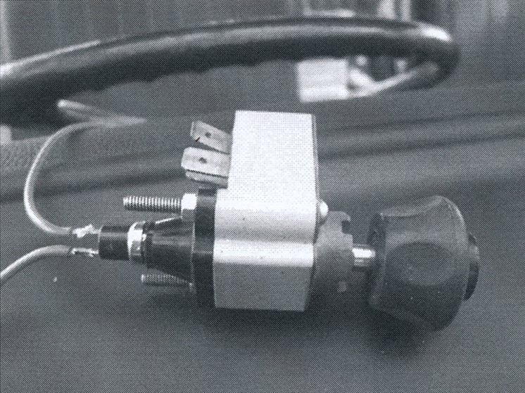
Screw the original front knob back in place and insert the front cover with the insert that will press against the micro switch at the back. You may find this plastic insert will need to be trimmed to size to make it sit in place and also be able to reach the micro switch. If the switch insert is a fraction too long, it will protrude too far from the front of the wiper knob. Remove the insert and trim the end closest to the micro switch carefully with side cutters to achieve the correct length.
With this done, place the switch to one side and focus on the rest of the job. You will need to install that windscreen washer motor at position lower than the washer bottle because these pumps aren't self-priming (which means these motors are unable to suck fluid, they can only push fluid once it has actually drained into the pump using gravity). The washer motor must be lower than the bottom of the reservoir so that water is in it at all times.
Before installing the washer motor look carefully at the pump for an arrow that indicates which direction of the pump is the ‘in’ and ‘out’ directions. These pumps only pump fluid in one direction, so you will need to ascertain which direction is correct before you mount the pump.
Another point to remember when mounting is that the pump MUST be mounted horizontally with the in and out fittings on the pump pointing horizontally. You must also mount it so that the electric part of the pump is higher than the impellor of the pump. If you fail to do this water may leak from the pump into the motor and short the motor’s electric circuit.
Connect one wire from the 12-volt windscreen washer motor you have installed, to an earth point on the body/chassis of the car. Next connect a wire from the other terminal of the windscreen washer motor, to one side of the micro switch you have adapted to the back of the original switch. This will require soldering. Then connect another wire from the other terminal of the micro switch back to the 12-volt accessories of the fuse box. That's it for the wiring.
Earlier you disconnected the flexible rubber fluid hose from the wiper switch at two points. You will need to trace which hose goes to the windscreen washer outlets near the windscreen. This hose is to be routed back to the 12-volt washer pump you have installed. Note this hose goes to the ‘outward’ side of the washer pump, or the side in which the arrow points. Finally, you will need to connect the inward side of the pump to the washer bottle. You will also need to vent the washer bottle so that a vacuum doesn't form inside the bottle when the motor is running. To do this simply unscrew the black plastic fitting on top of the washer bottle and remove the air pressure fitting that usually resides here. This is enough to vent the bottle sufficiently to atmosphere to prevent an air lock forming.
Reconnect the wires to the back of the windscreen wiper switch that you modified earlier and mount this back onto the dashboard. Fill the washer bottle with water (and add a cap-full of Windex or similar) if it has been drained, and reconnect the battery earth strap. With the ignition key in the accessories position and by pressing the factory knob in on dashboard you should hear the 12-volt motor run and prime with water for the first time. A second or so later you should have a stream of water on the windscreen, probably for the first time in years. And best of all you can stick it to the mechanic next time he carries out that pink slip and jokes about Volkswagen windscreen washers!
Parts required:
12 Volt Windscreen washer motor - $16.95
Push button switch - $2.20
2 metres of 5-amp wire - $4.00
Install time - 1 hour.
Next month I'll detail the same install into a Kombi or Beetle that has the washer switch mounted on the stalk of the steering column of the car, such as a Superbug, Type 3, and Kombi (1971 onwards)
How to modify those windscreen washers so they actually work! Part 2
By Leigh Harris
September 2005
A few issues ago I wrote a technical article on how to install a micro switch in the back of a standard switch on an early Kombi so that the windscreen washers work and look like a factory setup with no ugly switches.
In this issue I'll do the same but this time to a ‘70s VW Beetle where the windscreen washers are triggered by pulling back on one of the stalks on the steering column.
What I've outlined below is a step-by-step upgrade to install a small micro-switch in place of the usual pressure valve located within the steering column assembly of a 1970s VW Beetle or any other such Volkswagen such as the 1972-1978 Kombi, Type 3 etc. I have previously performed this modification on Belinda's 1303 Beetle and Dave Birchall's Type 3 wagon.
Pulling back on the steering column stalk to trigger the windscreen washers usually depresses a pressure relief valve. Instead we will replace this valve with a small micro switch. The steering column will look factory but the washers will work off a 12 volt motor instead of relying on the washer bottle being pressurised with air and the dashboard will look factory without an ugly switch installed elsewhere.
Firstly you'll need to buy a 12-volt aftermarket windscreen washer motor from an automotive shop such as Autopro or Super Cheap etc. I paid $16.95 from the latter shop. Then you'll need to buy a press button switch and some wire capable of handling just a few amps from Jaycar or Dick Smith. The switch I bought was from Jaycar (cat no: SP-0714), which cost $6.50. This switch is perfect for our use, as I'll explain soon. You will also require a small piece of aluminium approximately 15mm x 25mm. The piece I used was 1.75mm thick.
Firstly begin by disconnecting your vehicle’s earth lead from the battery for safety. Next ensure your front wheels are pointing directly ahead. When you finish the job you'll need to reinstall the steering wheel in the correct position, and obviously you'll want the steering wheel orientated correctly. Next you'll need to remove the steering wheel to gain access to the switch assembly. This is a very easy task. Firstly remove the plastic horn cover from the middle of your steering wheel.
To remove the steering wheel you'll need a socket to loosen the nut holding the steering wheel onto the spline of the steering column. Just loosen the nut BUT do not unscrew the nut all the way off the column. Next to remove the steering wheel from the column you will need to sit in the drivers seat and pull the steering wheel up off the column spline by pulling on the wheel gently. By leaving the nut threaded on the column a few turns when the steering wheel loosens, you won't end up hitting yourself in the nose with the wheel or landing in the back seat holding the steering wheel. You'll see what I mean when it loosens! When the steering wheel has loosened off the spline, undo that nut completely and slide the wheel of the column and put it in a safe place.
When the steering wheel is removed you'll be confronted with the column. Note the four screws that hold the assembly into the column.
The centre section surrounding the steering column is the steering column indicator assembly that lifts out of the column itself. To do this reach under the column and you'll see two plugs that connect to the indicator assembly. To remove these plugs pull them down towards the pedals to remove from the contacts. There is no need to label any terminals or plugs as they only fit on one way. Next you will have two rubber hoses that run up inside the column that carry water to the pressure switch from the washer bottle. Try pulling these hoses off the switch, but only after you have depressurised the washer bottle - if your bottle actually held pressure that is! If these hoses won't pull off the switch cut them as close to the steering column as possible. We will be using this hose later on so an extra length will make you job easier. Once these two plugs and two hoses are disengaged you can remove the indicator assembly by unscrewing these four screws. Once loosened hold each indicator stalk and lift from the column by pulling the assembly towards you.
Begin by unscrewing the two Philips head screws that hold this pressure switch to the assembly. Once this is removed you will need to snip and remove this small piece of plastic that once pressed on the pressure switches diaphragm. Note the small piece of plastic that looks like a small thumbtack that needs to be removed. To do this I suggest a small pair of pliers or side cutters.
Begin by cutting a piece of aluminium that is 2mm thick and cut in a size of 25mm x 12 mm. You will need to mark two holes 22.5mm apart then, directly between these two holes mark a third hole. But note these holes may vary from model to model. To check your distances measure how far apart the mounting holes were for the original pressure switch you just removed. The two outside holes need to be drilled to 3.5mm. The middle hole needs to be drilled to 6mm or the size of you switches outside threaded diameter. Be sure to mark these holes carefully and centre the job. If they are marked incorrectly you will need to modify later to make the assembly fit. One corner will need to be filed off to allow the switch assembly to fit inside the column assembly.
Next find the micro switch you bought and remove the plastic cover button and discard. Insert the micro switch into the middle hole of the aluminium and screw the switch up. You'll need to drill this hole out here to the size of the threaded part of the micro switch or thereabouts. To do this, use a drill on very low speed so as to not damage the small sliding plastic piece that will push on the micro switch when mounted.
Once drilled try fitting your aluminium piece with switch to the indicator assembly in place of the pressure switch that was once there.
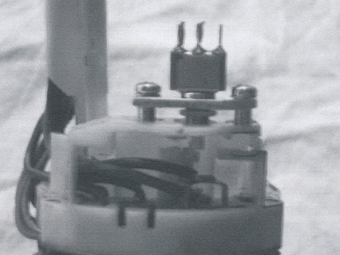
If installed correctly the holes should line up and the micro switch should be depressed. When the windscreen washer stalk is pulled you should be able to see or hear the micro switch being pushed in. What you may need to do is round off one corner of the aluminium plate you have made, as you will notice the plate protrudes out past the curved lines of the assembly that slides into the steering column. To do this, remove the switch and plate and file the corner off with a square file. Then re-fit to the indicator assembly for the final time.
Next solder two wires to the back of the switch. The wire of one-metre length should be soldered to the middle terminal, which will go directly to 12 volts at the fuse box. The other wire will go to either outside terminal and will need to be 2 metres long or long enough to reach the front washer bottle.
This can be installed back into the steering column with the wires poked first down the steering column where the rubber hoses once resided. Gently push the assembly home inside the column ensuring no part of your aluminium plate is fouling on the column assembly or plastic steering column covers. Tighten the four screws up, and reinstall the steering wheel, nut and steering column horn button.
The windscreen washer motor must be installed at a position lower than the washer bottle because these pumps aren't self-priming. These motors are unable to suck fluid; they can only pump fluid once it has actually drained to the pump using gravity. Look carefully at the pump for an arrow that indicates which are the ‘in’ and ‘out’ directions. These pumps only pump fluid in one direction.
Another point to remember when mounting is that the pump must be mounted horizontally, with the inlet and outlet fittings pointing horizontally. The electric part of the pump must also be higher than the impellor of the pump. If you fail to do this, water may leak from the pump into the motor and short the motor’s electric circuit.
Connect one wire from the washer motor to a suitable earth point on the body or chassis of the car. Next connect the longer wire from the micro switch to the other terminal of the wiper motor. Then connect the spare wire that runs from the micro switch to the car’s fuse box. It’s preferable to use the fuse for the ‘accessories’ terminal of the fuse box. Consult your VW’s workshop manual.
Earlier you disconnected two flexible rubber fluid hoses from the existing pressure switch on the indictor assembly. You will need to join these two hoses together under the dashboard, or if you are keen you can trace which hose goes back to the windscreen washers. This hose can be routed back to the 12-volt washer pump you have installed. Note this hose goes to the ‘outward’ side of the washer pump, or the side in which the arrow points. Finally you will need to connect the inward side of the pump to the washer bottle. You will also need to vent the washer bottle so that a vacuum doesn't form inside the bottle when the motor is running. To do this simply unscrew the black plastic fitting on top of the washer bottle and remove the air pressure fitting that usually resides here. This is enough to vent the bottle sufficiently to atmosphere to prevent an air lock forming.
Fill the washer bottle with water if it has been drained, and reconnect the battery earth strap.
With the ignition key in the accessories position, and by pulling back on the indicator assembly to trigger the micro switch you should hear the 12 volt washer motor run and prime with water for the first time, and have a stream of water on the windscreen probably for the first time in years.
Parts required:
12 Volt Windscreen washer motor - $16.95
Push-button switch (Jaycar Cat. No. SP-0714) - $6.50
2 metres of 5-amp wire - $4.00
Small piece of aluminium, 2mm thick (30mm* 12mm) - priceless
Install time - 1.5 hours