
Engines - General
Hope It’s A Life Sentence
Denzel Shopping Guide
Judson Supercharger
The Ideal Cylinder Size
Would You Believe ‘Stock’ 1500 = 100 bhp?
The Volkswagen Engine
VW Engine Disassembly
Engine Inspection
My Tech Teacher Would Have Been Proud
Starting Your VW/Audi
Keep Your Wagen Waggin’!
Low-budget 40-hp Hot-up
Building a strong, reliable VW engine
The VW Engine
Under Your Valve Covers
Type 1 Flat Four
The VW Boxer Engine
A Long Life for Air-Cooled Engines
How Turbochargers work
Performance Volkswagen summary
VW’s VR6 engines explained
Volkswagen TDI diesels
Volkswagen FSI technology
Golf TSI ‘Twin-charger’
Hope It’s a Life Sentence
By Dave Long
July 1987
Our VW Club’s stated aim is ‘Keeping as many Volkswagens on Australian roads for as long as possible.’ I often wonder how long ‘as long as possible’ might possibly be. For me, it’s a lifetime thing, and I hope it’s the same for the rest of you, at least the hard core.
To me, the VW Beetle pre-1300 and some of its brethren, especially the Karmann Ghia, are an institution, perhaps a way of life; holding on to cars like ours amounts to a statement of values, more simply nostalgia if you like. But I believe to preserve and operate an old Volkswagen is to hold on to an era. To adhere to that is to hold on to some of the magic of a span of years, roughly since World war II, so it can’t slip from our consciousness too easily.
Perhaps I am being subjective (I was born at the start of the War), but that’s how it feels to me; of course the People’s Car precedes that by several years, so that’s where the true beginnings lie.
So as not to offend too many, I include 1976, in Australia at least, to contain the ‘last’ of the genuine German VW Beetle.
My first Beetle was a 1958, Gulf Green I think from memory, which I was lucky enough to purchase in 1962 from its elderly original owners who lived a couple of doors up from my girlfriend’s place (later to become my first ex-wife!)
Beetles were already by then assembled CKD in Melbourne, from imported components (Completely Knocked Down), but the people at Clayton were doing an excellent job. They came together very nicely, if mine was in any way typical.
I would wish every VW freak the experience of just sitting in a well-kept early model, or preferably, though impossible, a new one, and breathe in the fragrances, feel the upholstery materials and touch the controls. Think of new rubber floor mats, spotless cloth roof lining, doors that fit so well you had to wind down the window half an inch before you could close them, such was the standard of dust sealing.
And if you were really lucky, maybe a Blaupunkt radio – the Frankfurt model perhaps, with a marine band for ships at sea, short wave, and FM before anyone knew what to do with it (it would receive TV audio signals, taxis and occasionally the police frequency). Lots of fun.
The seats of this imaginary car would be immaculate, with smooth pleats (no bumps in the filling) and kids haven’t got at the piping around the seat edges; ever thought how difficult it is to keep prying fingers off that stuff once a tear starts? It’s like not scratching a spot, or leaving a rough tooth alone!
Carpet would be new, and as for rust, happily such a car hadn’t even heard of the word.
You casually adjust the tinted celluloid driver’s sun visor, glance around at the almost total lack of instruments, turn the key, and away you go. The state-of-the-art RS4 Dunlop cross-plies hum quietly as you cruise along, mostly at 72mph on the clock, or faster if downhill. Uphill was, and still is, a different story, unless you swapped your 36-hp engine for a 1500, or an 1835 nowadays, shame on you!
I have to remind myself that the range of VW-ing now covers perhaps four generations. The younger ones will have been brought up on 1500 Beetles, 1970 or so, Type 3s (ahem) and the odd Karmann Ghia.
Some may only know the water pumpers, while those like myself can recall someone in the family maybe buying a brand-new showroom-fresh ’54.
The older ones from Europe perhaps even had Schwimmers or Kübelwagens down in the back shed. There are also a few lucky ones who served apprenticeships with VW Australia (a dealership, more correctly), some to the extent of serving at the factory at Wolfsburg for 6 months or so.
25 years ago I was scanning the Owner’s Manual of that first Beetle and wondering how the hell I could ever hope to do any work on it myself. It just looked so involved, especially the engine, since my very first had been an old MGY sedan – 4 cylinders, cast iron, straight up and down, really agricultural.
But I caught on quick, and with almost indecent haste was trying to discover how to get some performance out of the Veedub. First lessons were the limitations of the 36-hp; in its standard form the engine has few limitations, except, ironically, lack of power.
To tweak it, however, was not a task for the faint-hearted. You had to have money, and be very determined – mainly to have something that was pretty unusual at the time.
I understand that while most VW Beetle crankshafts were forgings, those of the 36-hp were forged at a lower temperature. They performed fine in mild to average use, but if caned, even within the reservations of eyedropper inlet ports and drawing-pin valves, they could break under stress from metal fatigue (flexing of the ‘shaft back and forth until it cracked in two).
The prescribed solution as a foundation for any hot-rodding was a specialised stroker crank, often such as the one made by Dr. Ing. Oettinger. Manufactured under the name OKRASA, they turned out an engine kit that did away with all but the basic crankcase, pushrods, conrods, flywheel, pistons/cylinders and valve gear/valve covers. It often used the standard camshaft, though a moderate grind was obviously of further assistance.
This kit had the first twin-port cylinder heads among VWs, long before the Factory introduced them. There were two single PIBC Solexes and a manifold for each head.
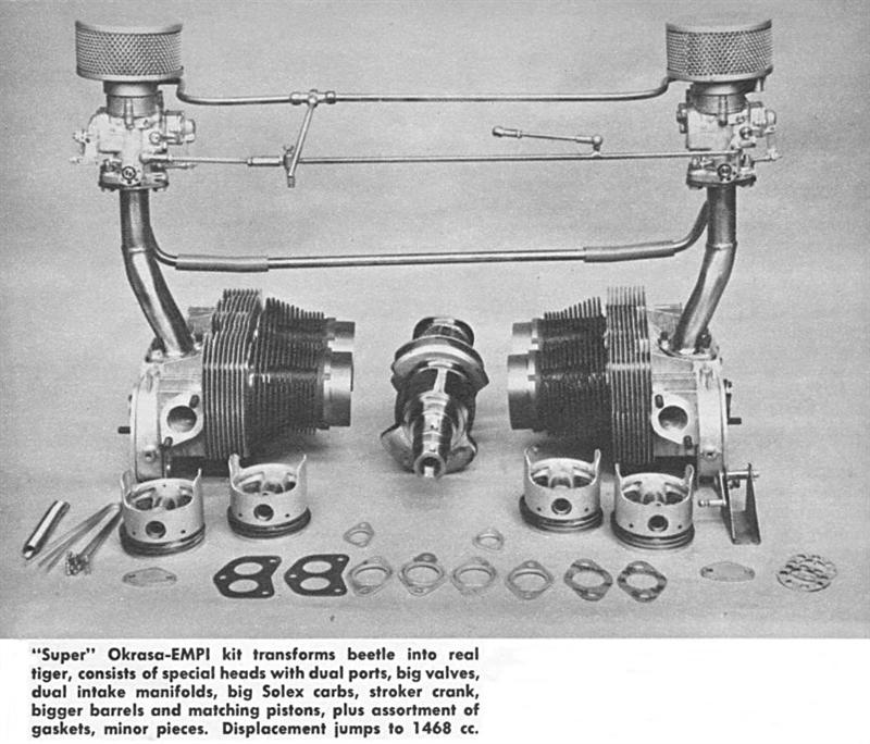
The crankshaft was a chrome-moly forging, 69.5mm as against the standard 64.5mm. Unfortunately, capacity was fairly well limited with the 77mm bore, to 1290cc. The engine was designated Okrasa TSV 1300/30 – TSV meaning Touring Sport Veloce.
Experimentation demonstrated that while 80mm was the theoretical maximum overbore of the standard barrels, 79mm was safer, and for an extra 60cc, who would bother?! I believe either no one knew how to machine the crankcase, or alternative cylinders were not then available. Of course, maybe there’s just no room.
Horsepower was 54 (SAE) and mine, in a sunroof ’60 model in 1964, with standard cam, covered a standing quarter in about 20 seconds (astounding, you say) and around 17 seconds for 0-60mph. It wasn’t at all bad for the time.
I was very happy until the advent of the Ford Cortina GT in 1965, then became a bit browned off. They got to 60 about a second quicker.
In those days (from about 1955) you could buy a new car and order it from the factory with an Okrasa engine. It was factory fitted and approved, and did not affect the warranty.
An alternative set-up further upmarket was the Denzel 1300 Super, made by Wolfgang Denzel in Austria. Some of these came to Australia. I don’t know how many, but they were rare because of the expense. A full-house Denzel engine from Jay-Bee Motors at Blakehurst, Sydney, was about 750 pounds when a brand-new Beetle was about 1150 pounds for the whole car. Luckily there were a few well-off desperates who bought them, or there wouldn’t be any around now.
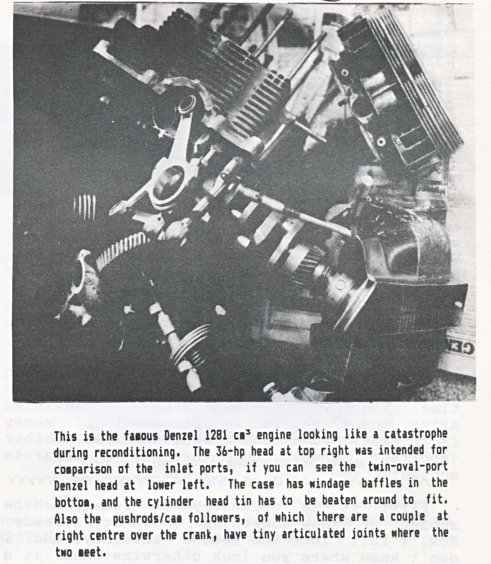
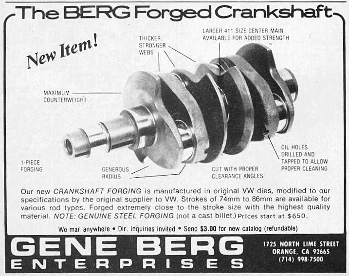
You could also buy just the Denzel crankshaft, which was a Good Thing. This was the heart of the Denzel 1300S (1281cc), and to the true enthusiast, the sight of one of these should bring tears to the eyes, It is a billet crankshaft; that is, neither cast nor forged, but machined from a single piece (billet) of highest-quality steel. This allows the grain of the steel to be closely determined, and ensures the finished article is virtually bulletproof. To look at it, it is stubby and quite heavy, probably 50% more than a standard crankshaft, with perfectly round counterweights and, like the Okrasa, eight-doweled during manufacture. The stroke is 67.5mm, three up on standard.
Cylinder heads are physically larger and squarer at the exhaust ports, due to more (and thicker) cooling fins, with valves about twice the standard area. Inlet ports are dual elliptical, perhaps even bigger than those on a 356 1600 Porsche. There are steel inserts in the heads for the case studs, and double counter-wound valve springs.
Other details inside the Denzel engine are cam followers universally jointed to the pushrods, eliminating any binding and ensuring you will never bend a pushrod, and chromed aluminium cylinder barrels, like an early 356 Super Porsche. Bore is 78mm, just to be different. Again, a bigger bore would have been nice, but who’s going to throw away the genuine item for cast iron 83s, or whatever.
The Denzel has two single 32 PIBC Solexes, just like the Okrasa, with slightly different jetting.
I am fortunate to have one of these engines, which is presently being rebuilt. It is probably my most prized possession, even ahead of the KG Cabriolet.
I know only one other of these engines – it is in a cut-down ’54 oval used as a shooting buggy (for foxes) in the Riverina, and the farmer who owns it won’t sell. Believe me, I tried!
Earlier I mentioned the crank could be supplied separately. This provided an unburstable bottom end without the expense of all the fancy bits. You could then supercharge, or something radical, getting mixture in the best and most cost-effective way you could devise and still get it down to the back wheels (provided you remembered to trick out the clutch).
The engine I have was run in a ’59 Bug in the very early ‘60s by two brothers named Ward. I believe Jim did most of the driving, while Colin kept it running. Jack Bono did the serious work. This car held the Up To 1300cc class at Silverdale Hill Climb for three years, 1960 to 1962 inclusive. It was finally muscled out by a supercharged 1100cc Goggomobil door-less Coupe, with I believe, a motor from a Bordward Hansa Tiger.
Determination and a lot of time/phone calls led me to the Denzel engine through a series of lucky breaks. By all accounts, Greg Mackie almost had it sewn up but the deal wasn’t completed somehow, then I came along with the right money and hauled it home from somewhere out Port Hacking way.
So, as you will see, I am in so deep I may not have enough lifetimes to do half the things I’m gunna do. Something that worries me from time to time is what will happen to it all when I am gone; there will be plenty of vultures ready to whisk it away, but let’s hope the ones carry on the faith appreciate what they’ve got.
My wife is slowly learning what everything is, and where it fits (fits?) so I hope she won’t just call in the scrap metal dealers for a price to crunch it up!
Denzel Shopping Guide
By Dave Long
May 1988
You will have gathered how proud I am of the Denzel engine, and I will attempt to give some of the history of this marque, which goes back more than forty years.
So far you may know only of the Denzel engine, but there was a Denzel sports car, of which a few survive. Those who follow ‘Hot VWs’ and ‘VW Greats’ may remember an article on the Denzel 1300 Sports Car a couple of years ago. You can count on more about that later. I want to describe how I located my engine and some of the factors that come into play when you are hunting rare parts.
Luck obviously comes into it a lot, but apart from needing the enthusiasm, it requires time, being available when the opportunities arise, and access to modest amounts of money (a friendly Bankcard). Negotiation is another important aspect, but that is a separate subject.
First it is necessary to research the subject or know something about it already. Now, I fall into the second category, and I don't know where you look otherwise, but it's all a matter of snooping around. Your telephone bill also takes a hiding, so you have been warned!
Let me describe some of my experiences, and you will see what I mean.
Getting in on the ground floor, when VWs were a car to do the shopping in, or win Redex/Ampol Trials, but usually in stock condition, has allowed me to build up a kind of mental scrapbook of the ‘ringleaders’.
When you are hunting for rare VW accessories, knowing your subject is important, but some detective work identifying an early source (like an agent or stockist) will narrow the field. If you can find the name of someone who once owned a car equipped with whatever you are looking for, he may still have it (unlikely after 15-20 years), can tell you who he sold it to (better chance) or has the number of someone who still plays with the same stuff (best of all). If he can’t help you, he may know someone who can. Don't give up too easily, be polite, but be persistent.
For years I have kept tabs on the various guys in the mainstream of performance equipment on VWs and four-cylinder Porsches. Their names come up from time to time, as occasionally they have cleanouts, and you have to watch the papers like a hawk !
Then there is the luck. Not long ago I bought a ’70 factory Convertible Beetle, and it was advertised in the Sydney Morning Herald on a Friday. I never watch the motor market on a Friday, but something made me do so this time. Going along on a Friday cut out the competition and the owner was keen to sell (it needs work). I honestly had to talk hard to line it up with the bank manager first!
Among my souvenirs is the makings of an Okrasa 1300/30 engine, which came my way through asking someone the right questions at the right time.
One of those mainstream guys I mentioned is Norm Campbell of Orange, who has been a VW motor dealer and enthusiast for the past 25 years at least. Norm is now nearing retirement age, and admits he doesn't have enough time left to do all the things he had lined up for himself (it will probably happen to me, so don't give up hope!) My philosophy is that whatever radical hybrid scheme might fire your imagination, unless the bits are available, you can forget it. Those ‘bits’ aren't getting any less scarce or expensive.
Back to Norm Campbell: late in 1986 he placed an advert in the SMH for some Porsche 356 gear - 1600 engine bits which were a bit expensive for me but I remembered a story that once did the rounds that he had on the shelf a Hirth roller bearing crank (a crippled one, no doubt.) So I asked him about it, and $200 later, he was putting it on the train for me, consigned to Hornsby.
Of course it was faulty, as they mostly are, but like I have suggested somewhere else, since they are no longer available, and we couldn't afford them if they were, it's the only way you'll get one. It has been away ever since at the crankshaft hospital, and I will be reporting on the result later.
In the same advert was a brand-new SPG roller crank to fit a 356 Porsche 1600 engine (as well as a 36-hp VW) for $1500! A guy I know who is a vet in Canberra bought it - he can afford such extravagances better than me.
It was Norm who told me where to shop for my Okrasa engine, some time in 1965. A plumber at Wellington, between Orange and Dubbo, had owned it since the early 60s, when it lived in a paddock-bashing Beetle which he used in local autokhanas and the like. When we went together to dig the bits out of the shed, I was in my regular state of combined apprehension and excitement. You have to be part archaeologist for this type of thing; only a fanatic would pick this stuff from the neighbour s garbage, but it was all there, albeit in need of help. The guy, to whom I am still grateful for selling it to me, in spite of the nostalgia which almost caused him to decline my miserable offers, was very proud that in the old days he had used exclusively a type of diesel oil to protect the engine.
But if you could have seen the baked-on mess, and the broken rings, I will stick to Shell, or GTX, or just about anything else.
The hunt for the Denzel engine was a quite different, and I think much more remarkable story. It was Jack Bono who first imported Denzel engine parts into Australia, and I found him again a couple of years ago.
Jack is another racer once from Orange, and he is back there again, but I believe he is now into a different kind of hot VW - in light aircraft. He is not the most communicative of people, but he did give me the name of a town in the NSW Riverina where he had sold an engine to a farmer, and the surname Ward, and Brighton-le-Sands, but that was all.
Remember from before, I said those engines were so expensive. That's why there were so few buyers. He also told me the Wards had a food business.
For perhaps 18 months that information sat in my book. I tried the Department of Industry for a check of business licences from the 1960s. I tried at random the phone numbers under ‘Ward’ in the telephone book no joy. Then one day in the Trading Post (of all places!) there was an advert for a modified 36-hp engine at Brighton-le-Sands. My reasoning went something like this - if anyone went to the trouble of modifying a 36, it probably had a decent stroker crank, either an Okrasa or Denzel, or it wouldn't have stayed together this long.
So you won't jump to any premature conclusions, this was nothing more rousing than a fairly bog-standard 36 that may have been balanced, that's all. The one good thing, it had an early Lukey exhaust with it -the twin-pipe model with adjustable tailpipes.
The elderly father of the engine's owner was selling it, and I just had to ask if he knew anyone named Ward who had been notorious for owning a weirdo hot Volkswagen (to digress, back in the 60s the Herald classifieds used to have a category "Hot" where you looked for modified VWs. They didn't show up often.) He had worked for years at the local dairy, and he remembered the Wards had either a delicatessen and/or a small goods shop. “Ring old Mrs So-and-so”, he said. “Jim Ward lives next door.”
Heart- in-mouth, I made the call, got Jim on the phone and confirmed (a) that they still had the engine (under his brother's house), and (b) there was no sentiment that would prevent them from selling it (it was avail¬able, in other words). After a few anxious moments I went to Oyster Bay one weekend and bought it.
Judson Supercharger
By David Birchall
November 1988
Haddon Judson of Conshohocken, Pennsylvania, USA (don't ask me to pronounce it), began researching superchargers in 1948 and designed the vane-type compressor pump about 4 years later. The Judson Research Company built ready to bolt-on kits for a variety of cars such as Volkswagen, Volvo, Mercedes and Renault. For those who are not aware, a supercharger or blower is anything that will force more air or air/fuel mixture into the cylinders of an internal combustion engine, than would be drawn into the cylinders naturally by the suction of the pistons during the intake stroke.
The Judson supercharger kits were designed to bolt directly onto the existing manifolding, and were advertised to produce approximately 5-7 psi boost (above atmosphere) output for most applications. The blower is driven at or close to the crankshaft speed by means of a vee-belt pulley system.

A cylindrical outer case with an inlet port on one side, and an outlet port on the other side spaced approximately 120 degrees apart, makes up the basic housing of the Judson. Inside this housing is a rotor that revolves on an eccentric axis. Four vanes protrude from the rotor and maintain light contact with the inner case wall. These vanes were inserted in slots in the rotor on an angle, so that the leading edge of the vane would be leaning in the direction of rotation.
The vanes were not fixed to the rotor, but when rotated held against the case wall by centrifugal force; yet, counterbalanced, so that they would not rub the case wall with too much pressure or friction.
Judson called the design, "balanced pressure". The big advantage of such a design is that virtually no clearances exist in the blower through which air can leak, therefore giving this type of supercharger a high volumetric efficiency.
The supercharger also required a constant supply of oil for lubrication when running. It is introduced into the blower below the carburettor and forced in via a vacuum into the blower housing. The kit comes with a glass storage tank and drip-feed system, where oil is consumed at the rate of approximately one litre per 1600 km. The oil lubricates the rotating shaft and spreads a thin film on the inner case wall to make the rotating vanes ride with less friction, thereby reducing wear.
The blower kits were available in Australia in the mid-1960s, and as with most kits, included the following parts: blower, oil lubricator bottle, air cleaner, drive pulley, vee belts, linkages and brackets, etc.
Nowadays finding a kit is difficult indeed. Most blowers seem to be in serviceable condition, but as for the rest of the kit pieces, most have been misplaced over the years. Kits were produced for the VW 36-bhp and 40-bhp motors. Some of Judson's claims on their sales brochure were: "50% more horsepower, amazing acceleration, surging passing ability, higher cruising speed, eliminating loss of power, better control for safer driving of your VW."
The Ideal Cylinder Size
By Rod Young
February 1990
Some writers have suggested that a cylinder displacement of 325 cm3 is the ideal for internal combustion motors. I can confirm that there are many automotive engineers who indeed feel this way.
I'm not going to argue that a small motor is better than a large motor, rather that an engine of a given displacement with ‘ideal’ cylinder volume is more efficient than a motor of the same overall displacement but a different number or cylinders. A comparison, say, between a 2.6-litre four-cylinder and a 2.6-litre eight-cylinder engine is valid for the purposes of this article.
Let's have a look at what makes a motor ‘good’. Many different criteria have to be considered here, some of which are partially mutually exclusive; in other words, you have to make a compromise. These criteria would be, amongst others, perhaps:
- high performance
- low fuel consumption
- low emissions
- low NVH (noise, vibrations and harshness)
- high drivability
- high reliability and durability
- low cost
- low weight
- compact dimensions
In the article I was reading, which was in an SAE journal about eight years ago I think, that along with a theoretical optimum displacement of 325 cm3, the ideal motor should have ‘square’ dimensions; that is, bore should equal stroke. (By the way, my memory is not exact, and I’m doing a little bit or surmising on the way).
Compared to other configurations, a motor with square bore and stroke would have the lowest ratio of internal surface area to volume. This means that the amount of relatively cold metal that the combustion flame comes in contact with is minimised, with good results for emissions and fuel economy.
There are other reasons for square dimensions being ideal. An ‘oversquare’ motor, ie. one with larger bore than stroke, must necessarily have a flat combustion chamber. This means that the flame front, after having been initiated at the spark plug, has further to travel to the limits of the quench zone on the periphery of the combustion chamber. If the flame has further to travel, it needs more time to do it. Then more ignition advance must be cranked in to allow efficient operation, and the more ignition advance use, the more efficiency you lose. When spark occurs well before TDC, the mixture starts to burn while it is still being compressed. This kinetic energy is much better put to use while the piston is on its ‘down’ stroke.

An oversquare motor unfolds its torque in a different way from an undersquare motor. This may or may not be desirable, depending on what the designers want. Simply stated, an oversquare motor has its torque peak biased to the higher end of the scale, ie. it is ‘revvy’.
An undersquare, ie. long-stroke motor, has other characteristics which make it less desirable than the ideal. Long stroke means that average piston velocity is high, leading to the motor wearing out sooner than it might otherwise. Air-cooled VW motors are definitely short-stroke, and therefore long lasting. Torque is delivered at the bottom of the range, which might not be all that a bad thing, depending on what is desired.
Now, let's go back to the ‘ideal’ displacement. If 325 cm3 per cylinder, ie. 1300 cm3 for a four-cylinder motor, is the optimum, then what happens on either side of this peak?
If you go above the 325 cm3 limit, the ratio of internal surface area of the combustion chamber to its volume increases - bad for fuel consumption and economy. The distance the flame has to travel increases, just like with a large-bore motor - bad for power and economy. If the cylinder volume really goes up, then NVH all increase as well. Extreme examples are Porsche s 944 (4-cylinder 2.5-litre), and Mitsubishi's Astron (4-cylinder 2.6-litre). On both of these engines, counter-rotating balance shafts are built in to counter the vibrations.
If you go below the 325 cm3 limit, the surface/volume ratio goes up again. The next effect is that mechanical losses, ie. friction due to the relatively large number of cylinders, rise as a proportion of overall displacement.
However, I'm pretty sure that the major effect is that of surface area. A lot of research has been put into modern motors to ensure that they have low internal surface area - hence hemispherical combustion chambers and four-valve-per-cylinder heads.
While the above might describe why the ideal is so, it's by no means so ideal that it's worth pursuing before other considerations. It's the sort of thing that can be considered when an engine is on the drawing board, but as soon as a manufacturer wants more power, they're just as likely to up the displacement and throw out the ‘ideal’ dimensions.
In the early ‘80s, GM was talking about building a family of odd-numbered multi-cylinder motors, all based on the ideal combustion chamber. Imagine a 1625 cm3 5-cylinder, a 2275 cm3 7-cylinder and a 2925 cm3 9-cylinder! Obviously, it didn't happen - they probably encountered vibration problems, and I don't know whether the 9-cylinder was an in-line or a V-motor!
Would You Believe ‘Stock’ 1500 = 100 bhp?
By Dave Long
February 1990
Scanning some old magazine articles recently, my attention was drawn to a piece to do with bolt-on modifications to an ordinary Type 1 1500 engine. This was Hot Rod magazine (USA), November 1969.
With a generous serving of scepticism, I present the following reproduction of the subject article for your enjoyment. Just to whet your appetite, the main caption reads: "43HP VW Bolt-On. Give that 1500 an impressive performance boost without splitting the cases or even yanking the engine." The ‘performers’, by the way, are big names, so maybe it isn't so far-fetched.
"Simply bolting on 43 horsepower to many large-displacement engines can often be a neat trick, but when you can pull this off with a 1500cc VW, you can figure that there was more than one trick involved. In this case there were three tricks - Dean Lowry, brother Ken Lowry, and their partner Gene Berg. These guys never seemed to work very hard at it, but when results count, it seems they try to corner the market on know-how and experience in wringing the last little bit out of a VW.
“We challenged the crew to bolt on horsepower that could be used on the street; horsepower strained through a muffler, horsepower that could be bolted on - which meant not having to pull the engine or split the case. Dean acts like it's no big deal, and we were figuring that he might be able to come up with 25 to 30 more horses - which would make a nice little story. But 43 horsepower? So pull up a transaxle and have a seat.
“The test series started with Dean strapping a 1500cc four-banger onto the dyno. After new points and plugs, and setting timing and valve lash to stock specs, the little mill coughed out 58 horses at 4000 rpm. Not bad. This was a used stocker - complete down to the rusted tips on the tail pipes.

“Run No 2 was conducted with the addition of Lowry's patented plenum ram intake manifold, topped off with a 32NDIX Zenith. Keep in mind as you go through this that the secret to horsepower is in getting the correct combin¬ation of components, so Dean slipped in a distributor from a 59-61 Transporter. The part number on this little jewel is 231 129 010. Twenty degrees of advance is all in by about 2300rpm. Experience has shown that the engine likes 32 to 33 degrees advance, so another 12 degrees was added at the crank.
“Back to the intake manifold, which from casual observation appears to be just another accessory manifold for a VW, until you take a closer look at the area just under the carburettor. There is a plenum here - a space common to both intake pipes. Testing has shown that this plenum is instrumental in eliminating oscillations of the fuel/air mixture, which is a normal result of the VW firing cycle. To further hone the combination of distributor, plenum intake manifold and Zenith, jets were changed to a 180 air correction and 145 main jet, and a 24mm venturi was substituted for the stock 25mm unit. With all of this in place, but nothing else, peak power of 67.8 was delivered at 4500 rpm. A check of the chart will show horsepower up over the entire range.
“Run 3 consisted of removing the stock exhaust system and bolting on Deano Dyno-Soars’ extractor exhaust, complete with muffler. With no other changes, the horsepower figure rose to 74.1 at 5000 rpm. Notice that horsepower decreased at only one rpm level - less than one horse at 2500 rpm.
“A small-diameter crankshaft pulley was added for Run 4. This is just under 6”, compared with stock pulley diameter of 7 inches. This smaller diameter at the crankshaft means the cooling fan is turning less rpm than before, which tends to reduce cavitation at high revs, producing more horsepower and resulting in better cooling. For stop and go driving, you might have some trouble getting away with this since we are depending on relatively high rpm operation to achieve the gains mentioned. Thus at five grand the pulley allowed five more horsepower (79.1) to move into the dyno. Tests have shown that you can figure on 11-horsepower gain if the engine will turn six grand. This one couldn't - stock innards remember?
“The Final test involved removing the cylinder heads for flycutting, porting and polishing. A straight cut is made down the cylinder-seating surface of each combustion chamber, to a depth of .100 inch. This raises the compression ratio to 9.2:l. When porting, Dean knocks out the area around the valve guide bosses, works to straighten out the port as much as possible, and opens the area around the intake port. The shop sells this machine work (which includes cc-ing) for either single or dual port heads, in case you don't think you can handle the job.
“When these heads went back on, a set of stronger, dampener-type valve springs went with them. Valves remain stock, but the seat pressure has gone from 70 pounds on the seat to 92. A set of 1.4:1 rocker arms from EMPI was snugged into place, and the jetting was changed to a 170 air correction and a 140 main jet. With everything else left ‘as was’, the 1500cc engine climbed right on up to 101.5 horsepower like that had been the plan all along – which it was, I guess; everyone sure acted that way.”
At 20 year old prices, by the way, without the cylinder head improvements and ratio rockers, the carb, inlet manifold, extractor, distributor, pulley and fan belt, the total parts bill was $US237.
An interesting article which contains some useful tips, but I wonder how they got the heads off ‘wthout pulling the engine"? The writer slipped up or got carried away. But overall, to place the result in perspec¬tive, compare the achievement of 101.5SAE/1500cc with 105SAE/1600cc of the Porsche 356SC/912. The VW engine appears to run standard cam but has 1.4 ratio rockers giving roughly the same valve lift as a suitable modified camshaft. It has single siamesed inlet ports and only a single dual-throat carburettor and manifold.
The Porsche engine has numerous advantages - near-hemispherical combustion chambers, huge twin inlet ports per head, bigger valves, counter-weighted crankshaft, twin dual-choke carburettors, plus the assumed Porsche refinement.
No mention has been made of torque figures, but I expect a 912 engine would be much easier to live with.
Either way, the result with the 1500 was a pretty good effort.
The Volkswagen Engine
By Geoff McVey
August 1991
The Volkswagen engine is precision-built throughout. Its reliability and economy are the principal reasons for the extreme popularity of this engine for many different uses the world over. Since the prototype was first shown to the public in 1937, there have been well over 30 million of these engines manufactured. Naturally the VW engine, with 50 years of background and experience behind its development, is today an engine that has been fully tested for reliability and durability.
This article assumes that the majority of the readers are not familiar with the VW engine, and it is therefore necessary to devote a portion of this article to engine description rather than to pure overhaul.
This view is further supplemented by the belief that with a basic knowledge of the design and construction of the engine, the reader will find himself in an infinitely better position to cope with individual and peculiar problems of overhaul as they present themselves.
It is hoped that this article will assist the ever-growing number of amateur VW mechanics who may wish to make some repair or adjustment to their VW power plants, or for that matter just to gain a knowledge of what powers their VW to its daily destination.
Design-wise it is a four-cylinder direct drive, air-cooled, valve in head, horizontally opposed engine, operating on the conventional four-stroke (Otto) cycle principle. All models are identical in general design, with only such changes in construction as to permit increasing horsepower rating.
A major change was made in 1960. The new 40-bhp (SAE) engine has an entirely new and larger crankcase. Magnesium alloy is still used, but wall thickness is much heavier than the 36-bhp model.
Although the bore and stroke remained unchanged, the cylinders were spaced 10 mm further apart. A new crankshaft was used, and though it looks exactly as before, the shaft is slightly longer, has thicker cheeks and larger bearing diameters. An entirely new cylinder head with smoother running wedge type combustion chambers was fitted, which allowed a compression ratio increase. Valves were made larger and it is here that the increased power and torque was obtained. The entire valve gear was completely redesigned, conventional mushroom-type tappets were used, and they lie in a true horizontal plane to ensure the same valve-timing sequence in all cylinders.
Later the VW 1300 engine with its longer stroke, and the VW 1500 engine with its larger cylinders arrived. In 1966 the VW 1600 engine was brought out, which was more powerful and has many refinements. It had (a) 7 more cooling fins per cylinder; (b) larger oil pump; (c) larger t cheeks; (d) bearing caps on the large end of the connecting rods, held in place with self-aligning bolts; (e) has a larger cylinder bore; (f) oil suction pipe is bolted down to the crankcase. In twin-port form, this is the finest and most powerful Type 1 engine Volkswagen ever built.
Crankcase
Structurally, the crankcase is a two-piece magnesium alloy casting, bolted together (without a gasket) at the vertical lengthwise plane through the crankshaft and camshaft, to form the complete crankcase. The two crankcase halves are aligned one to the other by use of two dowel pins. Rigid transverse webs hold the four main crankshaft bearing bosses and the three camshaft journal bosses.
These bosses, which are moulded in the crankcase, are line bored in the assembled crankcase castings (replacement must be made in pairs), to form bearings for the camshaft and seats for the precision main bearing inserts, and the precision camshaft bearings inserts in the VW 1300, 1500 and 1600 engines.
Tappet guides are formed in the crankcase in a plane below and parallel to the cylinders. The crankcase is drilled to provide pressure lubrication to the tappet guides, camshaft and main bearings.
The machined surfaces on which the cylinder flanges are mounted are called cylinder pads. Circumferential stiffen¬ing ribs under the cylinder pad give additional strength and stiffness to the cylinder hold-down bosses. Each pad has four hold-down studs per cylinder.
Crankshaft
The short, sturdy VW crankshaft is a high grade alloy steel forging, machined all over excepting some surfaces of the crank cheeks, and has wide-radii fillets between adjoining sections to reduce the tendency toward localised stress. The shaft is properly heat treated to enable it to withstand the stresses encountered. Main and connecting rod journal surfaces are hardened and ground to increase resistance to wear.
The shaft is drilled to direct lubricating oil from the main bearings to the connection rod bearings. All journals are situated in one place and require no counter weights. The finished shaft is balanced to a maximum imbalance of 0.12g per mm. The rear crank cheek is ground flat around the journal and contacts No. 1 main bearing (which is provided with flanges to take the end thrust). The thrust bearing is located between the rear crank cheek and flywheel.
Crankshaft end-play is adjusted by the use of shims located between the thrust bearing and the flywheel. The timing gear and fuel pump drive gear are heated prior to installation to obtain a shrink fit with the crankshaft, and are located with a Woodruff key. The smaller No. 4 bearing is located up front just back of the pulley wheel.
Connecting Rod
Short and rigid automotive-type forged connecting rods are used, with split precision bearing shells for the crankshaft journal, and a bronze bushing for the wrist pin.
Piston
The pistons are heat-treated aluminium alloy permanent mould castings. They are fitted with three rings; two compression rings and one oil control ring. The full-floating type piston pin is case hardened, seamless steel alloy tube, machined and ground and is secured endwise by circlips.
Cylinders
The cylinders are cast nickel-iron with cooling fins cast integrally with the cylinder. The close spaced cooling fins provide an ample and efficient radiation surface with a minimum resistance to air flow. This metal has the proper characteristics to withstand high temperature and give a good bearing surface. The cylinders are machined top and bottom, with the bore ground and honed to a smooth finish and held within extremely close limits. The two cylinder mounting pads on the left side are further forward than corresponding pads on the right side to permit each connecting rod to work on a separate crankpin. Each cylinder barrel is separate, and deeply spigoted inside the crankcase. A paper gasket is installed between the cylinder flange and the crankcase pad to seal against oil leakage.
Cylinder Head
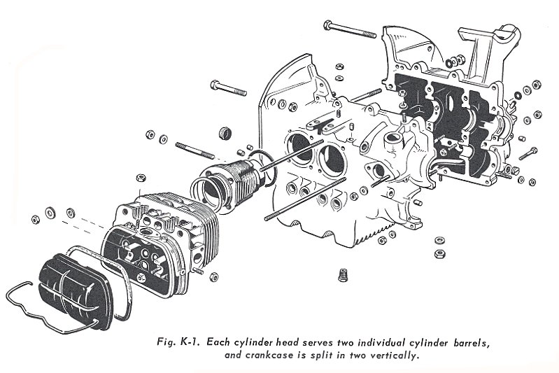
Each pair of cylinders has one detachable light aluminium alloy cylinder head, held in place by the combined strength of eight hold-down studs equally distributed over the head.
The two opposite and identical cylinder heads incorporate ample cooling fins, and contain two wedge-shaped combustion chambers with two valves for each cylinder. Bronze valve guides are replaceable, while the steel intake and exhaust valve seats are shrunk into the cylinder head. A spark plug hole is provided in each cylinder.
The rocker box is cast integrally with the cylinder head, and is provided with a cork gasket and lightweight pressed steel cover. They are scavenged by the draining of oil back to the crankcase through the push rod tubes.
The intake ports enter from the top and centre of the head casting, while the two exhaust ports leave in a horizontal plane; one front, one back.
Camshaft
The camshaft is machined on three journals, with four cam lobes and the gear-mounting flange at the front end. With the horizontally opposed layout, only four cam lobes are required to operate all eight valves. The lobes and journals are hardened and ground. The camshaft runs directly in the crankcase bore in the 1200 models, but later ones have replaceable bearings. A groove around the centre bearing passes engine oil from the right crankcase across passage to the left crankcase passages. A flanged front bearing (next to the timing gear) takes the camshaft end thrust. The front end is slotted to drive the oil pump.
Valve Mechanism
The overhead valves are situated in parallel in the cylinder head, but are inclined about 9° to the horizontal. The push rods are offset with respect to the valve stems, making it necessary to use diagonal rocker aims. The purpose of this is to bring the valve push rods and cam followers off the opposite cylinders in alignment with cam lobes on the camshaft, permitting one cam lobe to operate two valves in opposite cylinders.
Lubricating System
The system consists of a so-called ‘wet sump’, one in which the oil supply is contained in the bottom of the crankcase. From the lowest point in the sump, oil enters the lubricating system through a filtering screen to the oil suction pipe, which leads to the inlet side of the gear type oil pump. The pump is located at the front of the engine, next to the gear end of the camshaft from which it is driven.
From the pressure side of the oil pump, the oil is forced past the pressure relief valve, into passages drilled in the crankcase. If the pressure relief valve so allows, it then flows through the vertically mounted oil cooler that is always supplied by air by the engine-driven fan. Some of the oil is fed via the main bearings through the drilled passages in the crankshaft to the connecting rod bearings. Oil is also fed to the camshaft bearings, and through the hollow push rods to the rocker arms. Cylinder walls, pistons and piston pins are splash lubricated by excess oil from the crankpin bearings.
Oil returns to the bottom of the crankcase, where it is cooled by air passing over 460 cm2 of finned surface on the bottom of the crankcase.
The variation in the speed of the oil pump from idling to full-throttle operating range of the engine, and the fluctuating of viscosity of the oil due to temperature changes, are compensated for by the tension on the relief valve spring. The oil pump is designed to create a greater pressure than probably ever will be required, in order to compensate for wear of the bearings or thinning out of the oil.
VW Engine Disassembly
By Geoff McVey
November 1991
The first thing of importance is to provide a good clean working area with sufficient storage space where the parts may be kept clean until you are ready for reassembly. During the disassembly operation be SURE TO TAG and identify each part as it is removed and store in an orderly manner so they can be relocated correctly on reassembly.
A portion of the disassembly can be per¬formed while the engine is still in the car. First remove the engine lid, which makes access much easier. Parts that can be removed include earth strap, electrical connections, carburettor and air cleaner, distributor, manifold, fuel pump, coil, fan housing and generator, generator stand, fan belt, accelerator, heater and clutch cables and flexible heater tubes. Removal of these items helps reduce jacking height required for engine removal. The remainder of the work can be completed on a bench. An engine stand is not necessary, but makes things easier.
Remove the oil drain plug on the bottom of the sump and drain the oil. The valve covers should be removed, and oil allowed to drain from the rocker box. Replace the covers to keep out dirt.
Jack up the car and block at height required to lower and slide the engine out from under-neath. Check to see that all connections have been removed then place trolley jack under engine and remove the four engine mounting bolts that secure the engine to the clutch housing.
Place the engine on a bench, resting on wood strips, one on each side under the bottom of the sump, or bolt to engine stand.
Remove the rocker box cover from each cylinder head by swinging the bale to one side. The rocker arm mechanism is fastened to two supports on the cylinder head and is easily removed by unscrewing the two retaining nuts. Remove the rocker arm shaft and rockers as a unit. Remove the stud oil seals. Pull out the pushrods.
The rocker covers can be used to hold the rocker gear nuts and cylinder head nuts. Always replace wave washers on rocker shaft with new, and when replacing cylinder head nuts place the clean or shiny face down.
Remove the right cylinder head retaining nuts. Back off each nut a little at a time to release the head evenly all around. Lift off the cylinder head while holding the cylinders in place in the crankcase, using a clamping device. When removing the cylinder head place one hand underneath in a position to catch the push rod tubes should they fall out.
Remove the cylinder duct panels from underneath the cylinders. Mark and pull off each cylinder. Before removing a cylinder, rotate the crankshaft to place the piston in the cylinder to be removed at its top dead centre. Pull on the cylinder slowly, catch the piston as it emerges from the cylinder barrel and lower it gently until the connecting rod rests on the crankcase.
Mark the pistons to ensure correct reassembly. Remove the piston pin circlips with pointed nose pliers. Support the piston with one hand while pushing piston pin sidewise until free of the connecting rod. The pin should be kept with the piston in its normal position. If the piston pin is tight the piston should be heated to 96°C. With a soft aluminium drift, drive out the piston pin. BE SURE to support the piston while doing this.
To remove the cylinder head hold down studs, screw two nuts on the outer and pull them up together good and tight, then put your spanner on the bottom nut and back out the stud.
Remove the front oil pump cover nuts and pull off the cover with its gaskets, then pull out the gears. The hous¬ing can be removed with a special puller. Don’t use screwdrivers to lever against the soft crankcase. The pump housing fits tight in the crankcase so be careful not to scratch or damage the inside of the pump housing.
Remove the six nuts from oil strainer bottom plate, and remove the plate, strainer and gaskets.
Check to see that all items that are mounted across the crankcase parting line have been removed. Remove all the bolts and nuts from studs that hold the two halves of the crankcase together. CAUTION – it is so easy to overlook one that it is adviseable to go over this operation and check it thoroughly. Keep cam followers of left crankcase half in place by means of retaining springs.
Place the right crankcase on a block of wood at an angle of about 15°, so the crankshaft and cam¬shaft will not fall out when removing the left side crankcase. Use a rubber hammer to loosen the halves, and lift off left crankcase half. CAUTION - Do not insert sharp tool or lever between the joining faces to separate the halves or you will damage the sealing surfaces.
With the crankcase separated, lift the crankshaft, connecting rod and gear assembly from the crankcase. Lift by grasping no. 1 and 2 connecting rods. Check to see if the centre main bearing half came off with the left crankcase. If not, put it in the case where it belongs. Always keep split-bearing halves in their original location. Lay the crankshaft on a clean workbench with the front and rear bearing journals supported by wood blocks that have been grooved to a slightly larger diameter than that of the journal.
Lift the camshaft from the crankcase, and remove the cam followers.
Equipment, processes and materials in gener¬al use in motorcar engine overhaul shops will be satisfactory for cleaning VW parts. If you have access to these facilities you are lucky. If not you may be interested in the following.
The chief concern in giving this information is to point out certain hazards to be avoid¬ed, and call attention to the need for care in particular cleaning jobs, so that the rebuilt engine will be free of conditions which would lead to trouble, in so far as cleaning methods are concerned. CAUTION - Do not use gasoline for cleaning parts, due to the unacceptable fire hazard. Do not use any strong alkaline solution for cleaning aluminium or magnesium alloy parts, because all such solutions attack the bare surface too rapidly to permit cleaning without destruction to the finish.
CAUTION - Any alkaline deposit remaining on the engine interior parts react with acids formed in the lubricating oil to form soap, which will cause violent foam and may result in failure of the lubricating system.
The cleaning of the engine is divided into three parts. First is to remove all traces of old sealing compound from the joining faces of the crankcase. CAUTION - Do not scrape the joining faces to remove old sealing compound. USE A SOLVENT. Second is the degreasing operation to remove oil and soft sludge deposits from all parts. The third is to remove hard carbon deposits from the pistons, cylinders and heads.
CAUTION - The cleaning fluid must be of a type that will not attack metals, particularly bronze and aluminium or magnesium alloys, and be free from grit and dirt. Kerosene is generally good for degreasing where only loose solids and liquids are to be removed. Use a bristle brush to work the kerosene into and remove solid deposits. All oil passages in the crankcase and crankshaft should be flushed out with cleaner and compressed air. After the parts have been cleaned thoroughly, drain off excess cleaning fluid and dry with compressed air.
Soft and moderately hard carbon deposits may yield to solvents action, which should be tried first in preference to harsh methods. If this is not entirely satisfactory, it is recommended that the hard carbon be removed by hand scraping. Do not use a wire brush on pistons. Ring grooves may be cleaned by pulling lengths of binder twine through them. If it is necessary to use an automotive ring groove scraper, be sure that it fits into the metric dimension of the groove. Discolouration need not be removed from piston skirts. The use of abrasive cloth on the skirts is not recommended, because the diameter must not be altered.
Hard carbon may be scraped from valve heads with a smooth edge scraper, preferably while the valve is rotated in a high-speed lathe.
Removing hard carbon from the cylinder head's combustion chambers is a difficult job, but if you can rig up a cylindrical ring to fit in the head in place of the top of the cylinder to protect the sidewall, you can use an electrically driven wire brush. Even then it may be necessary to do some scraping in the low places.
Immediately after cleaning, bare steel parts should be sprayed or dipped in clean oil to prevent rusting, and all clean parts should be wrapped in plastic to protect them from abrasive dust in the air.
Engine Inspection
By Geoff McVey
December 1991
After the engine has been completely dismantled and the parts thoroughly cleaned and dried, place them on a clean table in groups for visual inspection. This inspection will be the basis for determin¬ing which parts have been defective or damaged in the course of operation. As they are examined make a list of all damaged parts and those worn in excess of the permissible tolerance, which must be replaced. Always number each new part to correspond to the number on the old part it is replacing. REMEMBER - serious failure very often arises from minor causes which a few minutes of inspection could have avoided.
Check the crankcase thoroughly for fatigue cracks. This should be done with the aid of a magnifying glass, in a well-lighted area. Examine the main bearing bosses for cracks, scratches and for size. Check that they have not been wobbled out of round. Compare the sides of the boss in relation to the centre size where oil grooves do not touch and are not worn. Check the dowel pins for main bearings and mating of the crankcase halves for tightness.
Check the camshaft bosses or bearings for wear or scoring. Inspect cam follower guides for wear. Check cylinder mounting pads for flaws or excess paint, and see that they are smooth. Check bearing surfaces for fuel pump drive. Inspect oil pump recess and flange surface for scratches.
Inspect the oil relief valve spring for a collapsed or worn condition. Check the relief valve piston for scores and free operation in the bore. Piston clearance is 0.04 mm to 0.05 mm.
See that all oil passages are open and check the suction pipe for tightness. Check all studs for damaged threads, bends and see that they are tight. Inspect parting faces for damage that might cause oil leak, and see that all the old sealing compound has been removed.
Inspect the cylinders for cracked skirts or broken fins. Check the cylinder bore for corrosion, scores and ring wear. Ring wear is evident by a ridge near the top of barrel at the end of ring travel. Use an inside micrometer to measure barrel bore about 12mm below the top and bottom end for taper, and at right angle to that in order to determine out of roundness. Difference should not exceed 0.1 mm for either wear or taper.
Inspect seating surface at top and bottom of cylinder for nicks and deep scratches, or residue gasket material or paint that would prevent sealing against leaks.
Examine the camshaft for wear of cam lobes and bearing surface. Check the rivets to see that the gear is tight on the camshaft hub flange. Check the teeth on the gear for wear.
Check for excessive backlash between crankshaft gear and camshaft gear teeth. The backlash should not exceed 0.04 mm. Place the camshaft between centres and use a dial gauge to check for run-out; maximum allowable is 0.02 mm. End play should not exceed 0.1 mm.
Check the face of the cam followers for wear. For good valve timing and volumetric efficiency, this face should be smooth and level, especially on the solid mushroom type used in VWs. Oil the followers and check clearance in guides in crankcase.

Check the inside of pump housing for damage. Check the drive shaft-to-housing bearing clearance by measuring the outside diameter of the shaft and the inside diameter of the housing bearing, which should fall between 0.038mm and 0.064mm. Inspect gear teeth for damage or wear. Check gears for freedom of rotation. Check pump drive shaft lug that contacts the camshaft slot for wear. Install the gears in the housing, and place a straight edge over gears and housing. Measure the clearance between the straight edge and gears (this should be between 0.03 mm to 0.07 mm). Check the cover plate for wear.
Inspect the oil bypass and sealing rings. Check the threads for oil press¬ure connection, and also threads on retaining stud and bolts.
Check the push rods for straightness and wear of ball ends. See that all sludge and gum has been removed from inside, so that normal oil flow to rocker arms and valves will not be restricted. Check the pushrod tubes for cracks along the weld seam. Always use new seal rings after an engine teardown if needed.
My Tech Teacher would have been proud
By David Birchall
October 1993
Way back in January 1981, I was working at Qantas in the heat treatment section when I decided that I had better update myself on the procedures and process of metallurgy. I had already been operating as the technical specialist in metallurgy for some 5 years at Qantas, but there’s always room for more knowledge.
I decided to try the TAFE metallurgy certificate course at Sydney college, which was only a short 4-year course. It was dreary start, but after 2 years it was finally starting to get interesting. Structures manufacturing process; casting foundry work; metallography; chemistry; the list goes on.
Then came Friday night class, 5.00pm ‘til 8.00pm, hosted by Dr Jules Vern, the classic teacher. No, not the author of 20,000 Leagues Under The Sea, but Dr Vern has written books on several subjects. He was a brilliant guy, and made the Friday night drag even shorter.
Jules made it all look easy, and really put you to the test in the metallography practical work. This involves the study of the structure of metals after various metal working processes, using high-magnification photography of metal cross-sections and the study of the grain structures.
Now we move to the present day. For the last couple of years, a fellow VW enthusiast (who will remain nameless, but has been around a ‘Long’ time) has been trying to convince me that an engine crankshaft that has been made from a piece of billet steel, by machining in a lathe, has more structural strength than the original VW process of drop-forging. Or, for that matter, any other engine crankshaft produced using this process.
Mind you, I listened to this guy every time he talked, like I listen to everybody else, but I also gave him the metallurgic theory point of view, which is that he was wrong, and VW-style forging is best. Alas, he was away with the pixies, so I demonstrated to him with a piece of timber, explaining the grain orientation of the timber, which is similar to a billet of metal. It shouldn’t have been over his head; it ought to have sunk in quicker and made him see the light sooner about the metal grain structure of billet extruded metal vs. dropped forgings, but to no avail.
Last August we were all at the VW Spectacular at Nambucca Heads, listening to Dr. Gene Berg at the seminar. These are always very entertaining and informative, with the audience in awe of Gene’s many years of VW-trained experience, expertise and friendly manner. Next question from the audience and it’s Mr. Billet Crankshaft. Oh no, he’s going to ask about billet v forged cranks! But that’s OK, because Gene Berg will always tell you that there is no such thing as a dumb question.
Actually I told him that one last time I was in Gene’s office in Los Angeles, but that’s another story. We also use that saying in the airline industry, which by the way is also where Gene Berg started off – at Boeing, in Seattle.
Yes, Mr. Billet Crank had his theory shot down in flames by Gene Berg. But that’s OK with me, because he did make an apology – much later. But I still don’t think he’s really convinced.
Anyway after all those years of Friday nights at TAFE, something really did sink into my old scone. Thanks, Jules, even though you thought I wasn’t listening to you, and my assignments didn’t always get gold-standard marks, I did pass all the exams – and the knowledge you passed on proved its value against Mr. Billet Crank!
Starting Your VW/Audi
By Rod Young
November 1994
It sounds like a straightforward enough topic - starting a car; something we all do every day, scarcely enough to warrant writing an article about, you would think. Well, if Phil Lord can write about ‘Cleaning your VW’, I thought there was more than enough scope for this topic. In fact, there’s enough material here to do the subject to death.
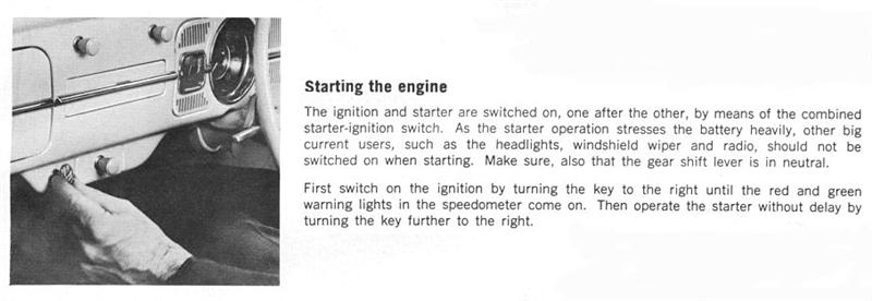
My Beetle instruction manual, dated August 1969, offers this advice for starting:
“Before turning the ignition key, make sure that the gear shift lever is in neutral.
“At temperatures above freezing point or when the engine is still warm, depress the accelerator pedal fully once and then release it slowly so that the automatic choke can work. Then switch ignition on and start immediately. Declutch so that the starter has only to turn the engine.
“As soon as the engine starts, release the ignition key so that the starter is switched off.
“Do not try to warm the engine up by letting it idle with the vehicle stationary - drive off straight away.
“Do not race the engine while it is still cold.”
As you would expect from the organisation that designed and built the car, this is the correct advice, but it does not stop many people from practising and advising other not-so-correct techniques.
It may be stating the obvious to many readers, but I will attempt to explain why the above advice makes perfectly good sense.
Depressing pedal slowly: For an engine to start in the first place, the air/fuel mixture at the combustion chambers must be in fairly narrow range, somewhat richer than for normal running. Too lean, and the spark cannot ignite the mixture; likewise for too rich, with the added danger of ‘flooding’ the engine - wetting the spark plugs and necessitating expulsion of the build-up of wet fuel. Depending on the temperature, more or less of the fuel will fall out as liquid, leaving a broad range of mixture strength available for the combustible part which comes into contact with the spark plugs. Then there are other variables apart from temperature such as carbon build-up and compression pressures. The point I am building to is that every start of every engine is different, and that different engines tend to ‘like’ a different amount of mixture entering the combustion chambers. The best way to cater for what any given engine likes is to begin turning the starter motor with the throttle closed. Whatever the engine likes, all the way to full throttle, will be chosen as the point at which it starts.
Pumping the throttle: Unless your choke is disconnected, this is not a good idea. At best, it is unnecessary, leading to wasted fuel. Between best and worst, it leads to an over-rich mixture, delaying the starting procedure. At worst, it can lead to flooding of the engine. How should you start an engine if it's flooded? Waiting a while helps. It's a bit hard to explain, but sometimes waiting only five or ten seconds can make all the difference. On other occasions, I have found, an engine that I had abandoned as un-startable has sprung to life easily when another attempt was made some hours later. The other thing you can do is to open the choke fully (may be difficult with automatic chokes) and turn the engine over with full throttle. This cleans out any accumulated liquid fuel until the mixture strength falls back into the range where it is combustible. If you have disconnected your choke or are running carburettors such as Webers which have no provision for a choke, then the only way you will start your engine is with a couple of pumps of the throttle to produce a richer- than-normal mixture. You will find with experience what the optimal number of squirts is.
Depressing the pedal fully with a cold engine: quite straightforward, really - this allows the fast-idle cam to drop past the throttle linkage, thus letting the choke valve to close and the fast idle to come into play.
Why you should de-clutch: When the clutch pedal is not depressed, the gearbox main shaft is effectively coupled to the flywheel, so that when you try to turn the engine over, the starter, already starved of current if the temperature is low, is forced to turn over gearbox shafts and gears coated in thick, cold, honey-like oil. Depressing the clutch will relieve it of this task and may mean the difference between starting and not starting. Sometimes you can see evidence of this effect - let go of the handbrake, turn the starter over with the gearbox in neutral, and the car may edge forward slightly.
Warming the engine by idling: Don't! Even though a certain well-known idiot’s manual recommends this, this practice is only for idiots. In order for wear to be minimised, the engine should reach operating temperature as quickly as possible. That means high combustion pressures, which only happens when you drive the car on the road, not when you let it idle in the driveway. Of course, you should minimise the chances for high wear by not over- or under- revving the engine during the warm-up process. If you leave the car to idle, not only will you make yourself unpopular with your neighbours, your engine will definitely not last as long as it should. Think about it - for a cold engine to run, it is doing so with the choke closed, therefore with a rich mixture. At the same time, very little oil is being thrown from the crankshaft onto the cylinder walls because the engine is idling and the oil is thick. What oil does reach the right place gets washed off with the rich mixture being created by the choke. No thanks!
If you own a latish-model VW or Audi, chances are it will be fuel-injected. The owner's manual for my 1984 Audi 100 states:
“Depress accelerator pedal slightly and keep in this position while starting. Turn ignition key and start up. If the engine does not start after ten seconds, wait about 30 seconds and then repeat the starting procedure.”
This works for me most of the time, I admit. I have a feeling that the factory only wants the throttle to be opened a small amount in case of backfire, which may damage the flow sensor in the fuel injection system. This can certainly happen with electronically fuel-injected engines, such as Type 2s. (I've got a collection of flow sensors with bent flaps). However, I have found with a friend's 1979 Audi that when the engine is very hot in summer, giving it full throttle helps it a lot to start.
I have had the recent pleasure (?) of working on a carburettor from a Golf 2, a fairly rare item which was never released on cars for the Australian market. They have an amazing set of controls for starting and cold running. Not only does it have an electrically heated choke, it is controlled by a thermostatic switch that delays its turn-on. Then the choke gets heated up by the engine coolant. (OK, some late Australian-released Golf 1s had both of the above). The designers must have found out that electrically heating various parts helps things, so they included the following: a very large heating element in the manifold, underneath the carburettor base, called ‘Igel’ in German, meaning ‘hedgehog’. This is turned on by a relay controlled by a thermo-switch in contact with engine coolant. Nice idea. Then there's an electric heating element in the side of the carburettor for the ‘part-throttle passage’ which is always on when the ignition is on. Next there's a fitting on the front of the carburettor into which coolant flows. I cannot work out which part it applies heat to. Fast idle during warm-up is taken care of by a great big diaphragm on the throttle linkage, which also controls anti-dieseling, overrun cut-off and idle speed stabilisation when an auto or AC are fitted. I know I'm digressing, but enjoying it.
By great contrast, I had the misfortune to be asked by an acquaintance with a late-70's Toyota Celica to look at the carburettor, as the car was stalling during warm-up and then running rich. I could not believe it when I found that the automatic choke had no electric element or coolant hookup, but relied on under-bonnet temperature alone for the bimetallic spring to do its stuff. Also, it had no fast idle system. Of course, it was not working. Rubbish!
What if your VW or Audi won't start? I'll skip the obvious stuff and assume that the starter motor is turning the engine over freely. I'll also assume that the points, if fitted, are in good shape and correctly gapped, that spark plugs are correctly gapped and the distributor cap is clean and dry. OK, that fixes 99% of starting problems already.
If an engine will not start despite your best attempts and everything else seems OK, try closing the spark plug gaps to 0.6 mm - it's amazing what a difference this can make. Don't clean spark plugs with a wire brush, as this may leave traces of metal on the insulator surface.
Unlike other cars, VW/Audis should give few problems with plug leads. German cars generally use a copper-core type of high-tension lead, which gives an excellent connection between coil and spark plugs. Radio-frequency suppression is provided by resistances in the spark plug and/or distributor connectors, which only occasionally play up. Lesser vehicles, by contrast, use so-called ‘silicone’ plug leads. The silicone refers to the insulation, not the conductor, which is no more than carbon-coated string. Avoid using this type of plug lead if possible, as they will have to be replaced eventually.
If the distributor cap is giving problems, it will mostly be obvious from a quick visual inspection. But there is one trap for the unwary, and I was caught out. Some years ago, I replaced the distributor cap on my Beetle, for reasons that now escape me. At the time I was using a capacitive discharge ignition system, which is capable of throwing a spark across very large gaps. All was fine for about eighteen months, then the car became hard to start, although no changes had been made in the meantime. A sharp-eyed friend of mine picked up the problem - he noticed that the brass contact in the centre of the rotor button was not shiny as it should have been through contact with the carbon brush in the distributor cap, but corroded. Yes, I had fitted the wrong distributor cap which fitted fine, but which was about 10 mm too high. The GDI did a fair job of throwing a spark the extra distance, but then things got too hard even for it.
After about 15 years of use, VW/Audi ignition switches can give problems. You may notice that the engine won't fire while the starter motor is turning over, but then catches as soon as you let go of the key. This is an indication of insufficient current getting through to the coil; as soon as the starter motor has cut out, more current becomes available for the coil and the engine starts. Another possible symptom of the same problem is a charge warning light that glows dimly and flashes in time with the blinker warning light. The obvious cure is a replacement ignition switch, though of course you could fit a relay to relieve the ignition switch of carrying so much current.
The same can occur with current getting through to the starter motor. You'll pick this up by the starter motor making a grating or hammering noise as the solenoid engages and disengages in quick succession. It's quite common for a relay to be fitted near the starter solenoid. The only problem I have with this is that the wiring should be of equivalent standard to what the factory would use, otherwise, some time down the track, problems that are difficult to diagnose may arise.
Air-cooled engines can be hard to start when the starter motor bushing is worn. This part is located in the bell housing of the gearbox instead of in the starter, as is more common. It is made of sintered bronze and can only be got out with the engine in place if a special extraction tool is used.
One problem I have come across a number of times is that an engine starts fine while cold, but then after about an hour's driving and a thorough heat soak, the starter motor turns over with difficulty or not at all. Most recently I've seen it on a 1984 Transporter. I'm still not sure of the cause of this problem, but the current theory I'm working on after talking to a few people is a bent starter motor shaft. I have not tried to confirm this proposition and still don't understand why it would only show up when hot, but that's all I have to go on at the moment.
If the engine is hot and won't start, it may be that vapour lock is the problem. This is quite common in the heat of summer with air-cooled engines where the owner has allowed various bits of tin, hose and rubber to go AWOL over the years. The fuel at the fuel pump gets hot enough to vaporise, preventing it from being pumped any more. It is more likely to happen after the engine has been sitting for a while, allowing heat to soak into it. The best solution is to fix the overheating problem; otherwise if the engine is allowed to keep running, more serious problems may arise. In the interim, cooling the fuel lines and pump with cold water will make a big difference. When trying to start a motor suffering from vapour lock, always use full throttle, even with fuel-injected engines, as this is the best way to get the liquid fuel moving through to where it's needed. K-Jetronic engines from after about 1983 are less likely to suffer from vapour lock, as they are fitted with an accumulator and injectors that maintain a higher residual pressure. Something else to check with K-Jetronic is the check-valve in the fuel pump and the pressure regulator in the fuel distributor. If either leaks, residual pressure can bleed off back to the tank.
Another problem peculiar to water-cooled K-Jetronic engines, especially those with 5-cylinders, is carbon build-up in the inlet manifold and ports. This acts as a sponge for liquid fuel being squirted out from the cold-start valve, preventing fuel from reaching the combustion chambers during cold starts. There is a factory solution - an additive that is squirted into the inlet manifold during running which cleans out some of that carbon build-up.
The cold-start valve and thermo-time switch are the components to check if cold starts are difficult on fuel-injected engines. These components are used on K-Jetronic (mechanical air-flow: Golf GTI, Audi 5-cylinder), L-Jetronic (electronic air-flow: Type 2 air-cooled ) and D-Jetronic (electronic manifold pressure - Type 3 Fastback ) , though the last uses a thermo-switch instead of a thermo-time switch. When VW used their own electronics instead of Bosch's in the case of Digijet (Type 2 1900) and Digifant (Type 2 2100 and on), they cleverly did away with both these components and used a longer-duration pulse at the injectors during cold starting.
Worst-case scenario: if the engine turns over fine but refuses to start, there is a good spark at the plugs, fuel is flowing in the right quantity and spark timing is right, you should look with much trepidation at the valve train system. I have seen failures here on both air-cooled and water-cooled cars. In both cases, the car stopped and would not restart. On the Beetle some years ago, all the obvious things were checked, then the NRMA mechanic looked inside a valve cover - nothing moving. What later showed up was that the pin holding the bottom gear in the oil pump had become loose, moved forward into the cam gear and snapped the cam. No other damage. On the Golf more recently it was a broken cam timing belt. At least this part is much more reliable than on some other manufacturer's products - Holden recommends that Camira timing belts be replaced every 40,000 km!
I could go on and fill this magazine with more anecdotes, and I have not even mentioned diesels yet! No, enough already.
PS! See next month for switching OFF your VW/Audi.
Keep Your Wagen Waggin'!
Some thoughts on tuning your VW
June 1996
By design, the VW Beetle is a low-budget automobile. Initial cost was low (by most standards), and maintenance expenditures are less than that required for most cars. However, when tune time crops up, it pays to know the dos and don'ts peculiar to the VW. We'll assume here that you are only moderately versed in VW tune-up work, and it's time to freshen your favourite Bug.
The two most common problems you might find concern spark plug selection, and ignition timing. Most guys buy the wrong plug for the engine. Because of the metric thread configuration, most replacement plugs won't properly fit the VW engine. Bosch, Beru and NGK are all acceptable, but we've seen some problems to date with other brands of plugs.
In this same category, spark plug torque levels should be followed closely to prevent cylinder head damage during installation. Normally, over-tightened plugs create a crack between the plug hole and the valve seats. Shop manual torque specifications should be followed closely.
Improper spark plug selection frequently puts a plug of incorrect reach into the engine. This means that a plug of excessive length will put a couple of threads into the combustion chamber, provide a convenient spot for carbon accumulation and improve the chance for plug thread damage when the plug is removed for service, as the carbon has a chance to chew up the aluminium thread material.
The second critical area concerns ignition timing. It seems that most people feel that performance will be improved by advancing the timing. The VW engine, because of its basic heat dissipation characteristics, has a bad pre-ignition problem.
If you advance the timing on any VW engine (race or otherwise) more than about 34 degrees total, you're asking for serious trouble. In our experience, you don't need to use a timing light. It's easier to use the marks on the crank pulley. One of the two marks is at 7 degrees Before Top Dead Centre, and the other is at 10 degrees BTDC. Simply set the engine on the 7-degree mark and adjust the distributor until the points are just beginning to open. Then, if you want, you can use a strobe or timing light to make certain that the first tuning mark coincides with the crankcase seam.
Of course, you must set the points gap before you fool around with the ignition timing. Remove, clean and carefully file flat your existing points, or better still lash out and buy a new set. Carefully set the gap at 0.4 mm (0.016") according to the instructions in your workshop manual.

Advance in the VW distributors varies from total centrifugal to total vacuum, to a combination of both. Early units were centrifugal only. Subsequent models were exclusively vacuum, and late models combine both methods. For most performance applications, the totally vacuum units are a waste of time. Since all VW distributors are completely interchangeable, early units can be used in later VW engines. For semi-performance applications, the late-model centrifugal/vacuum advance unit is a good choice.
Another problem relating to the ignition system concerns spark plug wiring. Actually, there's no way to hold the stock wiring in the air-shroud sheet-metal hole near the plug. The stock VW rubber tends to deteriorate, allowing engine cooling air to escape before it cools the cylinder heads, leading to an overall heating problem. Stock VW ignition wiring contains a small section of carbon in the insulator tip next to the spark plug. This carbon performs as a resistor in the circuit, but it eventually burns away and causes an ignition skip that can drive you bananas trying to locate the problem.
Companies like SCAT can supply an ignition wire set that includes wires, plug boots and grommets that fit the sheet-metal surrounding the engine block so that cooling air won't prematurely escape the engine and permit excessive heat build-up. These grommets (or lack thereof) are the only thing stopping me from buying normal hi-performance after-market plug leads.
Another area that falls into the ‘be bloody careful!’ department concerns the removal of the VW distributor. If the drive shaft starts to come out of the engine as you pull out the distributor, 9 times out of 10 the thrust washers underneath this particular piece of equipment will be dislodged and fall into the crankcase, lost forever unless you decide to remove the engine and split the crankcase. Normally this is not part of most tune-up work, so remember to be careful during removal of the distributor. There's also a small spring on top of the drive unit that holds tension throughout the entire unit. Many times when a distributor is removed, this spring becomes lost and the distributor shaft can move up and down during normal engine operation. Effective ignition timing is altered any time distributor can action varies from stock positioning.
Another critical area relates to the frequency of oil changes. In an air-cooled engine such as the VW, oil deteriorates pretty rapidly. This is especially critical if the engine is operated for long periods of time or if stock compression has been increased. Regardless of what the standard VW owner's manual says, you should dump the oil and change it at least every 3000 km (that's 1860 miles). There's only 2½ litres of oil in the engine when it's full anyway, and trying to extend oil changes to 6000-8000 km is foolish economy.
Also, when you change your oil, do it as it's done at a VW dealer. Pull the entire oil plate and screen from the bottom of the case and wash everything in solvent. Replace both of the thin paper gaskets that ride on each side of the screen assembly. Gaskets from '61 to present are all the same, but pre '61 engines (36-bhp) require a different style. Both are available at VW dealers or any well-stocked VW parts house.
But the real lifesaver on the VW is the use of some kind of oil filter kit. There are several good units available, even though they all bleed a portion of oil pressure by running a small orifice restrictor. Admittedly, you don't get the filtering that's obtainable on conventional sizes of automobile engines, but something is better than nothing, and you also get the added volume of almost 750 mL of oil.
You should also clean the oil breather tube prior to loading fresh oil in the engine. This tube runs alongside the oil cap. Condensation (moisture) collects in it, and the water collects dirt. Moisture can also collect at the top of the oil dump tube just below the filler cap. The next usual step is rust flakes and the admission of slivers of metal into the crankcase. Wiping this area free of moisture will prevent the formation of rust and its entry into the engine. Just keep in mind that air-cooled engines are not only cooled by air; they're also cooled by oil. Clean oil, proper temperature control and frequent oil changes will add meaningful life to any VW engine.
From the standpoint of valve lash, there are two basic settings. Since VW cylinder heads are aluminium, valve gap settings will open (rather than close up) as engine temperature increases. This is simply because the expansion of the head moves the rocker assembly away from the valve stems, and the clearance grows. For example, a cold lash of 0.15mm (0.006") can open up to as much as 0.5 mm (0.020”) after stabilisation of engine temperature.
At any rate, valve lash should be set at 0.15mm (0.006") cold for both intake and exhaust, even though most workshop manuals suggest 0.10mm (0.004"). Check and readjust if necessary every 5000 km.
Little trouble can be expected from the stock VW carburettor, but you might see a little performance gain by using the late-model 30mm (1500 and later) on pre '68 manifolds. Early carburettors were 28mm units, so use of the larger hardware can help upper RPM power. Specific carburettor jetting is best worked out for the climate in which the engine is being operated. Normally, stock jets range from 122 to 127. If you change to something other than the stock exhaust system, it's wise to go a little richer on the jet. Here also, experimentation is the best approach rather than specifying a particular size for everyone and their pet VW.
The early, fully centrifugal distributors can also be used in late-model engines if a little more initial spark lead is desired without boosting total advance out of sight. The fully vacuum units are difficult to make work right, so either the totally centrifugal or centrifugal/vacuum unit is better under any circumstances.
Actually, about the best suggestion I could give any VW enthusiast is to purchase one of several good service manuals on the market, and follow it as closely as possible. We see problems coining into the shop-every day that have been generated through a lack of fundamental understanding of the car, and I know that we would never see many of them if the owner had had proper instruction while he was attempting to work on his car. The better manuals have all the dos and don't dos as well as illustrations and photos. It ought to be a part of the car.
Some other thoughts on VW service, for your consideration:
* A handy spark-plug holding and reinstalling tool is a short section of rubber tubing. This sure makes plug installation quick when you're poking a plug into a blind hole behind the manifolds and air shrouding.
* Periodically, you should remove the cap from the fuel filter and eliminate any residue that may have found its way into the bottom of the chamber. Regular cleaning of the unit will assure properly filtered fuel to the carburettor and reduce the probability of a carb teardown to get the junk out that should have been stopped at the filter.
* Inside the distributor cap, check for damaged (or lost) carbon electrode in the centre of the cap and excessive buildup or erosion of individual plug electrodes. Also look carefully at the cap itself for any cracks in the material.
* Servicing of your distributor should also include checks for cracked point wire insulation, degrease of the point plate, and relubrication of the point arm rubbing blocks.
* Slight cleaning (by filing) of the distributor rotor will help current passage between the rotor and plug terminals in distributor cap. Don't get carried away, though, because you're fooling with an air-gap dimension that won't stand for a super enlargement.
Low-Budget 40-hp Hot-Up
By Lance Plahn
January 1998
It is common knowledge that during the early to late 1960s, VW Australia produced a healthy number of Beetles fitted with the 1200cc 40-bhp engine. As testimony to VW’s quality and superb engineer¬ing, many of these vehicles are still on the road today, some 35-plus years on. For many years they have been the backbone of the Formula Vee racers. However due to natural causes and age there is a slowly increasing number not making it back onto the road each year, and recently Vees have updated to later 1600 engines. The 40-bhp motor has proven to be an efficient and reliable motor for the most part; however early in the piece there were a few teething problems with camshaft troubles and rocker shaft stud breakage.
Over the years you may have been re¬quired to overhaul the engine. As part of this overhaul, one objective may have been to obtain more power, which is achievable. Nowadays many just simply replace their dead 1200 in favour of a later 1600, but due to the economic climate many owners cannot afford this luxury. There are a number of modifications that can be applied to the old 40-bhp motor during overhaul, in order to gain a little more power without sacrifice of engine reliability. Options listed are based on a full rebuild using standard components from later model engines, though high performance items are available at an extra cost. Some modifications can be applied when performing a top end overhaul.
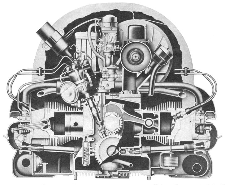
CRANKCASES: Due to age and high mileage it may be difficult to find a good used case to start with. VW ran the cam directly in case bores (no cam bearings), which created some problems. Naturally if the cam bore is worn there is a loss of oil pressure, causing further troubles. This problem was addressed by the fitting of cam bearings from the 1300 engine onwards. For best results, look for a case which has been modified to accept cam bearings. It is possible to use 1300, 1500 and 1600 crankcases, with the main difference being the barrel spigot bore size in the crankcase. The 1600 is larger than the 1200. VW Australia used a 1600, 3 point mount case on their 1200 Exchange Engines, and overcame this problem by manufacturing a larger 1200 barrel spigot. You may be lucky to find some of these barrels.
Another problem that surfaces at times is that the crankcases develop a crack at the lower end of No.3 cylinder behind the flywheel. This gives an annoying oil leak, often blamed on the crank seal. To prevent this occurrence in high performance engines, some builders elect to weld this area. But this is expensive and can create further troubles. An alternative preventative measure to welding, used by many Aus¬tralian engine rebuilders for a number of years, is to fill this area with Devcon F. This is an 80% aluminium putty which uses a hardening agent. I have had an engine develop this crack to which Devcon F was applied, allowing the engine to then run its full remaining life without replace¬ment of the case. Of course it depends on the severity of this crack. It is a good idea to address this problem before it occurs.
When assembling cases it is advisable to use nylon lock nuts (12x1.5) on the six main case studs. These nuts have a 19mm head as opposed to the standard 17mm. This enables a larger clamp area, along with a resistance to the tendency of the nuts working loose, thus avoiding any case fretting (the halves moving against one another).
CRANK: De-burr around the oil flow holes with an abrasive wheel on an electric drill. Mask the journals to prevent damage. Then clean holes using a rifle brush and cleaner. Carby spray is good for this job.
FLYWHEEL: The stock 1200 flywheel uses a 180mm clutch and weighs approximately 10 kg. A flywheel from a 6-volt Type 3 or a 1500 cc 6-volt Kombi accepts a 200mm clutch and weighs approximately 8.5 kg. These are interchangeable. The advantages gained are a lighter flywheel, which improves engine response, and the ability to accept a larger clutch to handle the extra power.
By now many owners have converted their electrical system over to 12 volts, retaining the 6-volt starter and flywheel. One problem experienced with converting this way is the starter tends to damage the teeth on the flywheel when engaging, thus requiring periodical replacement of the flywheel. You may consider using a 12-volt flywheel, with either 180 or 200 mm clutch. It should be noted the 6-volt crank and flywheel use a paper or steel shim between the two, whereas the 12-volt crank (cross drilled) and flywheel use an 'O' ring in the flywheel. The 6 and 12-volt crank shims are also different in size. If mismatched, this may develop an oil leak, which is often mistaken for crankcase leak. Some VW ex¬change engines utilised a 1200 cross-drilled crank requiring an 'O' ring seal type flywheel, although being 6-volt with 180 mm clutch. The 6-volt fly¬wheel has 109 teeth and the 12 volt 130 teeth.
Remember that if you use a 12-volt flywheel and 40-bhp gearbox you will have to grind the gearbox bell housing to accept the 12-volt fly¬wheel, and use a conversion starter bush.
The stock 1200 gland nut is tapered behind the bearing and tends to break on or before flywheel tension is obtained. Later model nuts are parallel behind the bearing and don't break as often.
VALVE TRAIN: Using a cam from a 1300/1500 or 1600 cc engine will give you a small increase in valve lift and longer duration over the standard 1200 cam, or if your budget permits you may consider a cam with more duration, say 15-55.
Cam followers from the 1300/1500 and 1600 cc engines have a thicker head than the 1200 and fit into the 1200 cases. However check clear¬ance between follower head and crankcases at maximum cam lift while cases are apart.
Stock 1200 pushrods are just adequate for the task as they flex at high R.P.M., resulting in loss of valuable valve lift. 1300/1500 and 1600cc pushrods are thicker and stronger than the 1200, but also longer. To fit them requires shortening, also allowing you to set up the rocker geometry. To shorten, carefully remove the aluminium tubing around the pushrod end to enable removal (a hacksaw blade is helpful with this task), then cut the tube to desired length. Place the pushrod end in the tube, while supporting in between two old cam followers, and use a hammer on the follower to which the end is to be fitted.
VW produced two different ratio rocker arms; a 1:1 for 1200 engines and 1.1:1 ratio as used on 1300/1500 and 1600 cc engines. Fitting the latter to a 1200 is a bolt on, but it may alter rocker geometry requiring the push rod length to be altered.
Valve springs fitted to the 1200 are a lighter spring compared to later model motors, with the later spring being identified with a purple strip. This spring is now sold as the replacement for the 1200cc.
Swivel-foot adjusting screws are an item used by many engine builders to reduce the pitting of valve stems (where the screw strikes the valve), plus side load and valve guide wear. This type of adjuster was used on early model Mazda 929s, so if you desire this item check out your local wrecking yard.
PISTON AND CYLINDERS: Increasing displacement is the most popular means to gain horsepower. The Hot Tip for the 40-bhp motor is the 83mm big bore kit that requires no machining to fit, increasing displacement from 1192cc to 1385cc. This kit provides a good power increase without any sacrifice in engine life, but real power gains can be obtained with this displacement when utilising other modifications as well, such as cam, heads, induction, etc.
CYLINDER HEADS: Cast on the head between the rocker posts is the part number for that head, 113101351, with a suffix lettering following, eg. A,B,C. These heads were continually being improved hence latter letters. Heads A,B & C (requiring a tappet clearance of 0.2 mm), suffered from breakage of rocker shaft retaining studs, necessitating a repair modified rocker stud. Head D and E (requiring a tappet clearance of 0.1 mm) were much improved upon, having a square block rocker shaft supports, additional cooling fins, strength and better flow characteristics. These heads are the pick of the 40-bhp head options.
Another head option is that from a 1300 engine. These heads (113101353B) have larger 33mm inlet and 30 mm exhaust valves, as opposed to 31.5mm inlet and 30mm exhaust valves use in 40-bhp heads, and incorporate a larger reshaped intake port along with better cooling fin design. This option will provide more horsepower than the 40-bhp head set up, but requires some modification to enable fitting. Some head stud lengths require altering, simply by obtaining head studs from a 1300 engine. The 1300 inlet manifold is larger in diameter and longer in length than the 1200 manifold, and will need shortening to fit a 40 HP motor with 1300 heads. To do this first you will have to melt off the heat rise pipe, then shorten the manifold to required length, then re-weld. This job will look neater if performed under the generator stand, or you could use a suitable flexible tube over the manifold then clamp it if welding equipment is unavailable. Finally, the rocker geometry may be affected, requiring different length push rods as described earlier in this story.
You may be lucky enough to find good 1300 twin port heads which also will fit, requiring much the same modifications as the single port heads. 1500 and larger heads have a larger barrel spigot in the head, as well as larger combustion chambers, creating further expensive troubles to fit, where as the 1200 and 1300 heads have the same sized barrel spigots.
INDUCTION: Horsepower gains from the 1200 engine are limited due to the manifold size. There is little gain if any by placing a larger carby on the standard 1200 inlet manifold. A larger manifold as used on 1300 or the 1500/1600 engines will improve flow of the air fuel mixture, but necessitating fitting of the 1300 heads. Then you can fit any carby from the 1200 to 1600 single port engines, or twin carbies from a Type 3 by using a 1500 or 1600 single port manifold. This requires reworking the Type 3 linkages and installation of sports air cleaners on tubing to clear the fan housing.
Carburation selection and jetting will depend upon engine modifications made, or performance factors you after. The numbers cast on to the side of the VW carby relate to throttle bore size. If rejetting is required the VW jets vary in decimals of 2.5, offering a good range.
DISTRIBUTORS: Like any other moving components they tend to wear out with time and usage, therefore requiring replacement or overhaul. The Bosch 009 is one replacement option. Its advantages are being relatively inexpensive, offering good life and mechanical advance only, making it ideal for use with replacement carburettors. There are disadvantages though. It is slow to advance from idle, giving a flat spot or making the engine sluggish off the mark. They have only one advance spring, and in some engines where the compression ratio, piston speed or cam timing is not ideal, this can create a pinging problem requiring the second or heavy spring from an old VW distributor to be fitted.
Another option would be to use a distributor from a 1600 twin port engine, which has both vacuum and mechanical advance. These distributors also work well, with the vacuum advance giving extra advance required when accelerating, passing and climbing hills. One problem experienced with these distributors is some tend to over advance, resulting in decreased perfor¬mance in the top end. Check to see if advance delivers more than 30 degrees crank degrees, if so limited the amount of advance movement in the distributor.
If you have an engine that can rev hard you may experience ignition point bounce, restricting high R.P.M. The answer is to use points with more spring tension. Instead of using the usual Bosch GB534 points, replace them with GB752 that are identical but heavier spring tension, as used in Porsche 911 and XU1 Toranas.
COOLING: As we know, the VW engine is both air and oil cooled. Air cools the external components and oil cools the moving internal components, with the aid of an oil cooler. The stock cooling system is adequate for its intended purpose, but must be in optimum condition for prolonged engine life, especially if the motor is modified. This starts by ensuring all cooling tinware is there, fitted and sealing correctly.
Over the years as the vehicle requires work, many parts may have been swapped, changed or left off. One part that has found it way onto some 40-bhp motors is a 36-bhp cooling fan. This fan is identical in size to the 40-bhp unit, except it has every second fan blade missing. It would be wise to ensure you have a 40-bhp fan.
The best cooling option would be to use the cooling setup from a twin port engine, requiring the dog house-style fan housing, chute and duct for oil cooler, rear tinware, oil cooler and stand plus wider cooling fan, displacing more air. To fit the oil cooler the crankcase mounting holes and bolt need modifying, including the correct oil cooler seal selected. On later model Beetles using this set up, VW installed extra vents in the boot lid to feed the larger capacity fan, so if you use this cooling option it will be advisable to place extra vents in the boot lid. This can be achieved by using a front vent panel from a Kombi, grafting the louvre in the boot lid.
With all this newfound power, the brakes and handling may be inadequate, thus requiring im-provement, but that's another story. Keep it upright on the black stuff!
Building a strong, reliable VW engine
By Lance Plahn
March 1998
It seem that every VW owner has dreams about putting together the ultimate motor, one that has the ability to blow away V8s, be streetable, achieve fantastic fuel economy, be inexpensive to build and, most importantly be trouble-free and last forever. Costs involved in a standard rebuild soon shatter most dreams, however, putting the notion of a high-performance or dream motor even further out of reach.
Let's face it - some VW models have, by now, been to the equivalent of the moon and back six times. This year, the year 1971 Super Bug and it's twin-port motor will be twenty-seven years old. But don't make the mistake of thinking that just because your engine is ten to twenty years old, the price will reflect the cost of that era. It's also not likely that the engine has clocked a high mileage and may already have been overhauled several times, thus necessitating the replacement of major components this time around.
So let's consider what you should do when overhauling a VW motor. After dismantling the engine, give the components a light clean to enable a visual inspection and measurement procedure to be carried out. Now, let's consider each of the components in turn.

CRANKCASES
Bolt the case halves together, using the six 12 mm studs and torque to specifications and, looking down the crank tunnel towards a light, verify whether the case halves are touching. If they're not, the cases are now junk - as the case halves have worn or are wrapped around the six main studs and will not produce proper bearing crush. If they are fine, have the halves acid-bathed, which removes sludge from the oil galleries.
Next, crack test to see if the halves are free from fatigue cracks- if cracking is apparent throw the cases away, as welding is not really successful. Bolt the case halves together, and measure the diameter of the main bearing holes with an inside micrometer. If oval, not within factory tolerances or uneven where the main bearing sits, the crankcase will have to be align-bored and the thrust faces cleaned up. This will mean over-size bearings (over-size on the rear and thrust).
Volkswagen over-size main bearings increase in graduations of 0.5 mm, with Repco bearings going over 2.5 mm (!) For best results, use good quality German bearings, but remember that they only go to 1.0 mm. It also pays to have the cam tunnel honed, which brings the tunnel back to specs and does not require over-size bearings.
Now check the barrel seats on the case halves. Sometimes the barrel pounds into the crankcase, with visible results. If this has occurred, the seats will have to be machined - this will of course, reduce the deck height (the distance from the top of the piston to the top of the barrel) and, in turn, increase compression ratio. Check deck heights on assembly and if necessary, fit the required spacer shims under the barrels to obtain the desired compression ratio. The head shims from a 1700-2000 Kombi motor are sometimes useful for this purpose, or you can buy them from good VW parts shops.
CRANKSHAFT
Check the dowel holes at the flywheel end of the crank, ensuring that the dowels fit firmly and that the holes are not elongated. Similarly, check the flywheel. If the dowels look worn, are marked or don't measure up to a new dowel, replace them. If the holes are enlarged or out of round, you can have them re-drilled at 45-degrees around from the existing holes. But, for best results, find another crankshaft.
Measure the crank journals, ensuring that they're up to specs and that the journals are not oval. Grind the crank, if required, but first crack test - as cranks do break! If cracked, replace. When the crank is ground, a good crank grinder will make all the journals the same diameter and to the maximum allowable tolerance and radius the ends of the journals. This reduces the chance of cracking. Deburring the oil holes in the crank eliminates any sharp edged or burrs resulting from the grinding. The crank should also be acid-bathed to remove and sludge in the oil galleries.
CAMSHAFT
Place the camshaft in the #3-4 crankcase-half with new cam bearings and check end float (you can use a feeler-gauge strip between the cam bearings and cam thrust face). If not within specs, you will have to replace the cam. Next, measure the three bearing journals and, if not within specs, replace. Check the condition of the lobes, looking for pits or deterioration on the case-hardening. If this condition exists, you can either buy a new cam or have your cam reground to standard or performance specs.
When replacing cams, ensure the required backlash between the cam gear and the crank gear is obtained. Incorrect backlash will cause the cam bearings to prematurely wear. The cam gears are numbered and range from minus 7 to plus 7, enabling the correct backlash to be obtained.
CAM FOLLOWERS
To check, place a straight-edge across the centre of the cam-follower head. As the head is curved, the straight-edge should touch in the centre. You may choose to place the cam-followers head to head, in order to get the same result. If the head is flat or concave, it will require attention and the followers may be radius-ground by a machine shop. By now, most have been ground a number of times and are at the limit of the case-hardened surface. Grinding also alters the follower length, resulting in differing rocker geometry. The other alternative is to purchase new followers and, for best results, select good quality units as the cheap ones can wear quickly, causing a lot of trouble.
CONNECTING RODS
Gudgeon pins should be a firm fit in the little-end-conrod bush and should not be too loose or able to rock. A new gudgeon pin should be used for this test but, if the old pin is to be re-used, measure it to be sure that it is the same diameter in the centre as at the ends. The bush should be tight in the conrod. If it's worn or loose, it should be re-bushed and reamed to suit the gudgeon pin being used.
Torque the big-end cap to the con-rod and measure the inside diameter-checking for an out of round condition and also ensuring that the diameter is within specs. If outside tolerances, the machine shop can re-size it by machining a small amount off the conrod and cap, making the hole smaller and then rehoning to specs.
This does alter the rod length (centre of big-end to centre of little-end) and weight. A good shop will get the four rods to the same length, upon request, by off-setting the hole in the little-end. It is advisable to have the rods balanced, bringing the weight differences back to specs. Alternatively, new aftermarket rods may be purchased. If they don't come in matched sets of four, as in the case of genuine items, it would pay to have lengths and weights checked. Varying rod length result in varying deck heights and compression ratios from cylinder to cylinder. If the rod weights are not within tolerance, bearing life and engine vibration just above idle would be effected.
PISTONS AND CYLINDERS
In most cases, it costs nearly as much to overhaul the pistons and cylinders as it does to purchase new units. If a piston has seized, a valve dropped or anything drastic along these lines has occurred, you will have to fit new pistons and cylinders. If you intend to use your old units, first check the piston and cylinder clearance, as either or both may be worn and thus make them unserviceable. Check for scours in the barrel, or seize marks, or both. Look for cracks in the piston skirts.
It is advisable to fit new rings, cleaning up the ring grooves and then fitting the rings to the pistons using a feeler-gauge strip to check ring groove clearance. If excessive, the ring groove will have to be machined and a spacer fitted. You should remove the carbon from the piston and, of course, clean everything.
If the heads have been compression leaking between the heads and barrels, the top of the barrel that seals against the head can be damaged and result in recurring leaks, if used again. If damage is minimal you may get away with rubbing the barrel on wet and dry emery paper placed on glass. If the damage is more severe, the barrel may require lathe-work. If this is the case, you will have to take the same amount off each barrel to keep all lengths equal. If they are different lengths, they won't seal, resulting in a head leak. Facing the top barrel will reduce deck heights and, if too much is removed, the piston may hit the head. Check the measurements and, if required, place shims under the barrels to obtain the desired deck height and, thus, a safe compression ratio. The cylinders will need honing to allow the rings to bed in. Cleaning the external barrel surfaces also aids proper cooling.
CYLINDER HEADS
Head failure features prominently in many engine rebuilds - leaking or cracked heads that result in loss of performance, burnt valves, loose valve seats or guides and even dropped valves. For best results and engine life, fit new heads. These are available complete or bare (no valves or springs). Reconditioned heads are available at cheaper prices, but don't give the service life of new heads-however, the reconditioners may dispute this.
Now, let's look at what's involved in overhauling heads. After dismantling, beadblast the heads and check for cracks. These have to be ground out and welded. Next, check valve guides for wear and replace if necessary. Measure the valve stems to monitor wear, replacing where necessary, it's advisable to replace exhaust valves as a precautionary measure. Ensure the valve seats aren't loose.
If the head has to be welded, it may be necessary to replace the valve guides and seats, as they have to be removed prior to the welding process. The valves will have to be syncro-seated (the valve and valve seat are cut to provide 100% sealing on contact) and the valve springs checked for tension and free length, as a weak valve spring can cause a valve to burn.
Check threads and studs that may need repairing (for example, damaged or stripped exhaust studs and stripped threads) a stripped thread being easily repaired with a heli-coil. The heads will have to be fly cut, the surface the barrel seats against being machined to ensure a seal. Welding or fly cutting the heads alters the combustion chamber volumes and it is advisable to check the capacity of all four chambers for variations. Variations mean different compression ratios from cylinder to cylinder and the engine may not run smoothly, which could lead to premature engine failure.
If the capacities do vary, they can be balanced by taking small amounts from the chambers with the lower volumes. You will need to know the head volume to check the compression ratio. It's more than likely that the compression ratio will be higher than standard after an overhaul and high compression ratios coupled with the reduction of lead in the fuel will only lead to premature head and piston failure.
OIL PUMP
Often likened to a human heart, the pump keeps the oil circulating. If it stops or slows down, expect trouble and, as it's realistically priced, it's advisable to replace it. The pump body is alloy and does wear and scour. Using a feeler gauge, check the clearance between the gears and the pump body and between the gears themselves. The gears rub against the pump cover, scouring it and resulting in reduced oil pressure. Replace the cover if it's scoured. Another component often overlooked during motor overhauls is the oil relief valve (and spring), a cheap component to replace. The relief valve or piston does wear and the springs do lose their tension.
MISCELLANEOUS
Rocker shafts also need a check. Disassemble, clean and reassemble. Check the wave washer on the rocker shafts, as they do wear and then break - allowing the rocker to float causing trouble. The tappet screws do wear or pit, so replace where necessary. The rocker shaft can be worn due to the rocking motion of the rocker itself. Replace if worn.
Give the push rods the once over also, checking for pits or damaged ends, bent or damaged shafts - caused, for example, by the push-rod tube rubbing up against the push-rod. Hold the push-rod up to the light and look through it. Notice the sludge and dirt. Carby Cleaner is helpful in cleaning the insides of the push-rods or, indeed, any other oil circuitry components. Push-rod tubes tend to develop small rust holes and then leak oil, or suffer from rock damage due to their position. Its' advisable to replace them and eliminate any troubles, as they're cheap enough. If reusing the old ones, inspect thoroughly for rust holes or cracks in the concertina at the ends, clean the tubes (a bottle brush is helpful) and beat out any damage.
During the reassembly of the motor, it's a good idea to use Nylok lock nuts on the crankcase halves, especially the six main 12x1.5mm studs. You should always use new conrod nuts. Check the condition of the head washers (they should be flat), as they tend to dish and scour the surface as the nuts are tightened. Replace as necessary.
Well, as you can see, there's a lot to do and check during a motor overhaul and money, or the lack thereof, will govern how much you do and how long your engine lasts. Just whacking in a set of rings and bearings is only a short term fix, enabling you to sell the car and, at least, get the new owner home. It's worthwhile remembering that the life of the motor will not only depend upon the components overhauled and the use of quality parts. All the tin-ware will need to be fitted properly and the engine serviced at the proper intervals. Then you will enjoy the benefits of your engine overhaul for many years to come.
The VW Engine
By Edward Eves
February 1999
Born as a piece of political machinery, the VW has been described as not so much as a way of life. It is powered an unusual and expensive to make four cylinder engine, air cooled with horizontally opposed cylinders. Capacity started at 986 cc, has been doubled in the 2-litre Kombi, and closely copied in the Wasserboxer 1.9 and 2.1-litre engines. Ferdinand Porsche investigated some interesting power units before this configuration was decided on. It is now a legend.
It is difficult but fascinating to try to unravel the very beginnings of the VW engine. It is easy to say that Karl Rabe and Xavier Reimspiess, under the direction of Ferdinand Porsche, designed a 985cc horizontally opposed, four-cylinder, fan-cooled engine to power Hitler's KdF-Wagen – the Strength through Joy car.
But the events that led up to this choice of configuration are tantalising and obscure. Long before Hitler came to power, Porsche had designed outstanding four- and six cylinder Austro-Daimler water-cooled aero engines, and then went on to design a four cylinder boxer air-cooled engine for the same company in 1912. He had been taken with the idea of streamlining as a means of saving power. As early as 1924 his business manager, racing driver Adolf Rosenberger, had raced the rear-engined Benz Tropfenwagen, which, in turn, had been inspired by the teardrop car built by Rumpler-Berlin in 1917.
Undoubtedly the Rumpler convinced Porsche about easy-to-propel streamlined cars, while his work on air-cooled aero engines (which are essentially slow running and reliable, with good torque at low revs), convinced him that this type of engine would be ideal to drive a low-drag car, given clear roads. The creation of the autobahn system fulfilled the latter requirement, and the request from Hitler to design a People's Car gave him the chance to bring the low-drag low-power car to fruition.
Very few designers produce a clear-cut design first go. Although Porsche had designed 1500cc horizontally opposed engine for NSU in 1933, a variety of engines was tried before the horizontally opposed four-cylinder configuration was chosen for the KdF Wagen. Most mundane of the projects was a boxer twin, which was discarded on the grounds of lack of flexibility. The most interesting was a four cylinder two stroke in which two of the cylinders acted as pumps. It suffered from overheating, probably because there was no bulk of oil to carry heat away from the pistons. Most extraordinary was a twin cylinder, single sleeve valve unit which had a habit of breaking the sleeve connecting rods, whereupon, as the ultimate triumph of hope over experience, Rabe tried to actuate the sleeves with cams and torsion bar springs.
Development of these engines was stopped in 1936 in favour of the now classic air-cooled four. Cylinder dimensions of the prototype were fixed at 70 x 64 mm giving a capacity of 985cc, but Daimler Benz only built a limited number of these units as propulsion for publicity cars used by the Nazi Party hierarchy. The larger 75 x 64 mm engine was developed for the military Kubelwagen command cars and the fascinating Schwimmwagen, which were the only VW vehicles to be made in the Wolfsburg plant before the end of the war.
In the bleak post-war years the tooling for this engine was all that was available, and was naturally used to produce the engines for early post war Volkswagens.
Over the years the VW engine has changed only in detail. Short overall length and low weight were and are main design perimeters because of the need to reduce the polar moment of the car in view of the overhung rear engine position. It therefore has a magnesium crankcase and light alloy cylinder heads. The opposed cylinder layout keeps length to a minimum and the weight in the right place, low down. Designed in 1936 when 30-bhp was considered plenty, the crankshaft was indeed short of bearing area if attempts were made to produce more power, as some tuners found to their cost. The major power increments in the VW coincide with the availability of high duty bearing material, and in 1961 by an increase in the length of the crankshaft.
The crankshaft nose, supporting the accessory drives, is part of the same forging and supports what is effectively a fourth main-bearing. The timing gears and the distributor drive gear are mounted on the section of shaft inside the chamber, and the fan pulley externally on the end of it. The crankcase is split vertically, each half including half of the bearing housings for the crankshaft and camshaft. The two halves are tied together with long studs passing horizontally through the bearing diaphragms and by nuts and bolts at the flanges. Although this construction precludes removing the sump (as it is part of the casting), cleaning is no longer a problem with modern oils and the layout makes for a very rigid crankcase. An inspection plate is provided in the bottom of the sump through which some cleaning can take place.
Separate cast iron cylinders are used with one-piece heads, the whole assembly being held down, motorcycle fashion, with long studs, eight per side, tapped into the crankcase. The unusual port layout, with vertical inlet tracts and with the exhaust ports coming out of the ends of the heads, is necessary to maintain exhaust pipe ground clearance and also allows the pushrods an unobstructed passage to the valve gear. The camshaft is located under the crankshaft. Oil return from the rocker covers is by way of the pushrod tubes, which are inclined to facilitate the process. Pressed steel rocker covers retained by wire dips seal the rocker chambers, which are partly formed in the cylinder head castings.
With these slow running engines, long accelerating and decelerating ramps are not required on the cams so the valve tuning appears less extreme than it really is. The early 1130cc engines had inlet tuning of 2:37 deg. and 37:2 for the exhaust. This was opened out to 6:35 (inlet) and 42:3 (exhaust) on the 34 bhp 1192cc model. As a comparison the 411 engine has inlet and exhaust openings of 4:39 and 40:3 deg. respectively.
Combustion chamber shape is exceptional these days in being a quite straightforward truncated pent roof type with the valves parallel with the cylinder axis but offset slightly below it. Early engines had flat top pistons giving a compression ratio of 5.8 to 1 in deference to the low octane value of the fuel then available.
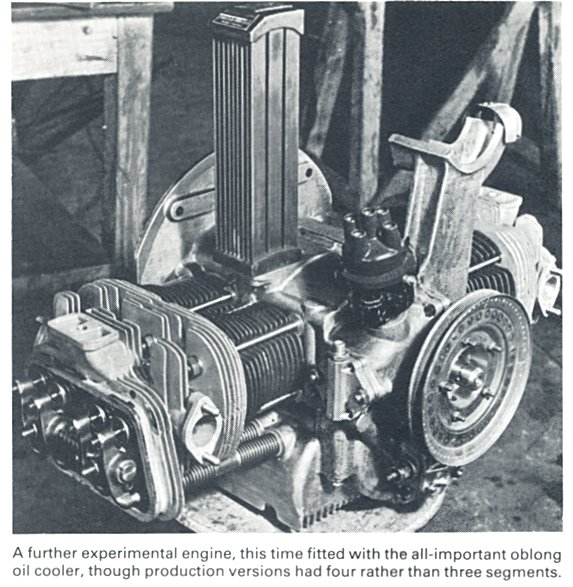
Lubrication is by a gear type pump, driven off the end of the camshaft. From the outset the VW has had an oil cooler mounted in the cooling shroud. Porsche no doubt deduced from his experience with the two-stroke prototype, that an air-cooled engine mounted at the back of the car, out of the airstream, must dispose of some heat by way of the lubricating oil. This is born out by the Porsche racing cars, which have oil coolers almost as big as the coolant radiator of a liquid-cooled engine.
On all early engines, and on most of the latest ones, mixture is supplied by single carburettor, of Solex manufacture, mounted on an exhaust-heated manifold fabricated from steel tube. This manifold is so like a pair of sit up and beg bicycle handlebars that one British engineer on seeing it remarked, that he supposed the sports model had a fully-dropped manifold. To eliminate icing, and to evaporate loose fuel the manifold hot spot extends almost a third of the length of the horizontal section of the manifold and consists of a steel tube siamesed to the main tube by welding. An early attempt to make an exhaust heated jacket on early 1192cc cars ended in failure. The exhaust gas burnt through the inlet manifold, thoroughly upsetting the carburation and many thousands of manifolds had to be replaced by the old type, which is still used.
At one time it was considered inadvisable to fit twin carburettors to standard VW engines, probably because of the marginal bearing loadings. But the 1200, 1300, 1500, 1600, Type 4 and Wasserboxer engines do not suffer from this shortcoming. Porsche experimented with cast iron crankshafts in the prototype stage and they broke, since when all VWs have had forged crankshafts. The connecting rods are likewise steel forgings, split at right angles with fully floating gudgeon pins and diecast light alloy pistons.
Cooling air is circulated by a centrifugal fan, supported by a cast bracket on the crankcase, and working in a sheet metal housing on top of the engine. On the 36-bhp and early 40-bhp motors a thermostatically controlled annular throttle ring in the inlet trumpet regulates the amount of air passing through the fan. On later 40-bhp and 1300, 1500 & 1600 cc motors, vanes inside the duct share the air equally between the two cylinder banks and act as thermostats flaps. On 36-bhp and early 40-bhp motors flap valves in the exit duct below the cylinder allow part of the waste hot air to be channelled to jackets surrounding the exhaust pipes, where it is heated further and fed into the car heating system.
When Porsche showed his proposals for this power unit for the KdF-Wagen in 1936, established German manufacturers threw up their hands and said "this aircraft engine" could never be made for the price. Any production engineer would say the same today if he didn't know that VW production tooling had not only made the whole thing possible, but also had made it an extremely worthwhile proposition.
Under Your Valve Covers
By Bob Donalds
November 1999
There is no substitute for experience so I thought that I would share a few of those experiences which you might find useful and prevent you making the same mistakes as me. In other words, some lessons are well learned. I have made most of the mistakes one can make under the valve cover, and I have reviewed the remains of other people's mistakes. For instance, rubber mounted rockers when the wrong rocker gaskets are used by mistake. Do you have any oil leaks?
What is so complex about the stuff under the valve cover? Looking at it you see a metal cover, and the spring clips (bails) that hold it on. Some aftermarket valve covers (usually the leaky finned cast alloy ones) bolt on to the head instead.
I have made some expensive mistakes with valve covers that I have installed. One such example comes from my racing days. One day at the track just before the race, and after adjusting the valves, I reinstalled the valve covers on a Formula Vee engine. I had done that many times before. No big deal, right? I found out the hard way that I had got it wrong and the valve cover was leaking. The car was smoking in the hard right turns. I had not checked the covers for leaks. I lost the race, the crankshaft, and the connecting rods. However I gained experience, which has lasted 20-plus years - check your valve cover for leaks every time you reinstall them. That means let it run and look to see that it is dry. It may take a few minutes for the oil to get up to the cylinder head. This effort is well worth the wait.
When installing the valve cover, always put a fresh gasket on! I do not glue them on so I can't get them off later. Just a thin smear of grease on both sides is enough. If it still leaks, try a new bail. They are less that two dollars at your VW dealer and they hold the cover tight against the head. You may find that the valve cover is just too old, rusty or bent. Try another one.
So your heater box is wet with oil, and you're sure the cover isn't leaking. Push rod tube gaskets and lower head studs can be responsible. There are expandable push rod tubes to repair any leaks that come from the tubes or tube seals. When rebuilding air-cooled engines I seal the studs inside the valve cover with silicone (non- corrosive kind). This could also be done at any time if the parts are free of oil. By the way, on some of the early 36-hp engines the lower cylinder head nuts had an O-ring that seals the lower stud holes.
Adjusting those valves must be the simple part, right? So you’ve adjusted your valves, but they sound like the Hammers of Hell? What gives? The answer may be the head temperature. The valve lash increases with temperature on all but the oldest stale air engines with long rocker studs. Anytime the oil temp goes over 100 deg C the cylinder heads can overheat and that can show up as a noisy valve train.

Perhaps the engine is not too hot but one or two valves are ticking away. You've gone back and tried adjusting them again and you are sure that the valves are set correctly but the ticking noises remain. What to do? One possible answer is that the valve is not adjusted to the clearance of the feeler gauge you've used. In other words, your valve tem has worn into a slight dish shape rather than being flat, and the feeler gauge simply bridged the dish in the end of the valve stem.
Since the tip of the valve stem wears over time, it's possible the feeler gauge can not flex enough to accurately reflect the true lash the rocker will have, and thus you get the ticking noise. Try adjusting it by feel with no feeler gauge. The rocker needs to move about the thickness of a plastic dollar note (0.15 mm).
Lash caps are one way to deal with valve stem wear. These go over the stem and give you a flat surface. The rocker stands may need to be shimmed to make room for adjustments. I shim the rockers on every engine I build to set the geometry. Every manual covers geometry, but not many of them deal with worn valve stems in-situ.
You should note that repeated loss of valve clearance, especially on the exhaust valve, indicates stretching valve stems or valve seat erosion. It is then time to remove the engine and heads for inspection, and a proper valve job.
If your axle tube boots are torn or leaking, action should be taken without delay. Delay could mean a new trans! Replacement VW boots are split so they can be installed without taking the whole axle assembly apart. If you've already been faced with this task, you know the working quarters are definitely cramped. The difficulty is compounded because as the suspension drops when the car is jacked up, the boots stretch because the larger and smaller ends are no longer parallel. You have to stretch your new boots into position and clamp them, then fasten all the screws and nuts to close the boot, and that isn't as easy as it might appear.
To keep the suspension from dropping when the car is jacked up, place a spacer between the spring plate and the stop (I’ve used a ½-inch socket extension) before jacking up the car. This will keep the suspension and axle from dropping when you do jack it up, and will take the tension out of the stretched boot. It will also give you a measure of added working room.
Type 1 Flat Four
By Neil Birkitt
May 2000
The VW Beetle and its derivatives have many unusual design features, not least of which is the engine. The Volkswagen flat four bears more resemblance to motorcycle or aircraft engine design than to that of a conventional car engine.
The design of the engine actually owes much to its location at the rear of the car. It had to be short, to keep overhang to a minimum, and also light in weight to reduce handling and weight distribution problems.
Thus it uses a horizontally opposed cylinder layout to reduce length and also maintain a low centre of gravity. Weight is kept down by the use of light alloys for the crankcase and cylinder heads and by using an air-cooling system, which is also better suited to the rear engine location.
The original VW engine design dates back to 1936 and is generally credited to Karl Rabe and Xavier Reimspiess, working under the direction of Dr Ferdinand Porsche. The original version displaced only 985 cc, by the use of a 70 mm bore and 64 mm stroke, but was subsequently enlarged to 1131 cc by increasing the bore to 75mm, and then to 1192 cc (77mm bore).
The 1200 was redesigned in 1960 with the same bore and stroke but output went from 36-bhp to 40-bhp SAE. In Europe this later 1200 was to remain in production throughout the Beetle's long history, although in Australia it wasn’t sold after 1966. Other versions of the engine grew to 1285 cc (1300), 1493 cc (1500) and 1584 cc (1600).
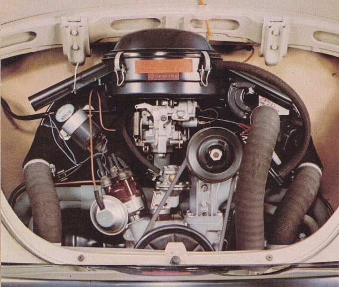
Over the years of its development the VW engine has changed in many details (mostly improvements!), although the basic construction is still the same. Visually, there is a considerable resemblance between the modern engines and the original prototypes of nearly 60 years ago although few, if any, parts would still be directly interchangeable!
The following description applies primarily to the Beetle (Type 1) engine, although the same unit has also been used in the Type 2 and 3 models, albeit with revisions to the ancillary equipment, cooling system etc.
The engine is based around a light magnesium alloy crankcase. This is constructed in two halves, split vertically and held together by six large studs in the area of the crankshaft housing. The case carries bearings for the crankshaft and camshaft, and the bottom of the crankcase also serves as a shallow sump for the lubricating oil.
Crankcases are sufficiently similar between 1961-on engines to be virtually interchangeable. Indeed, from 1970 onwards a ‘universal’ case was available for all usages, including Type 2 and 3. The only noteworthy variation is that from 1970 larger oil passages were used and the case has an additional oil pressure control valve.
The crankshaft is a short strong alloy-steel forging with all big end journal centres in a common plane. Four main bearings are used, with a thrust bearing (No.1) directly behind the flywheel. The crankshaft also carries drive gears for the camshaft and the distributor, as well as a pulley for fan belt drive to the cooling fan/ generator. Only one true oil seal is used, at the flywheel, while the pulley end of the crankshaft bore is sealed by a crude but effective oil slinger disc and a return thread on the shank of the pulley.
Two sizes of crankshaft are used, 64 mm stroke for the 1100/1200 and 69 mm for the larger engines. There are minor differences in the mounting of the crank to the flywheel occurring in the late ‘60s engines, with a rubber 'O' ring being used after May 1966.
The flywheel itself is secured to the end of the crank by four 8-mm dowel pins and a large gland nut tightened to a massive 295 Nm (217 ft-lbs) torque. Two clutch sizes are commonly used: 180 mm for 12/1300 engines and 200 mm for 15/1600 engines, with a 215 mm clutch being used on late model Type 2 versions only.
Flywheel ring gear size is loosely related to the change in voltage of the electrical system in 1967 (1968 in Australia), from the '6 volt' 109 tooth to the '12 volt’ 130 tooth gear. These changes limit straightforward engine interchangeability between these models.
The camshaft is housed in the crankcase directly below and parallel to the crankshaft from whence it is driven at half engine speed by a large aluminium gear wheel. The camshaft runs in three pairs of split bearing shells, though prior to 1966 the camshaft rode directly in the crankcase with no separate bearings.
The camshaft design is unusual in that there are only four lobes - each one operates valves on both sides of the engine via cam followers, pushrods and ratio rocker arms.
The cylinders are individual finned iron castings, which seat between the crankcase and cylinder heads. Three different bore sizes are used: 77 mm for the 1200 and 1300 engines; 83 mm for the 1500, and 85.5 mm for the 1600 engines. The 1200 cylinders are, however, different from those of the 1300 due to the shorter stroke crankshaft.
There is some interchangeability and both the 1300 and 1500 engines can be easily uprated to 1600, the latter by simple substitution of the larger 85.5 mm pistons and cylinders.
The pistons are light alloy with three rings and are secured to the connecting rods by a free-floating pin held in place by circlips. The standard pistons are flat topped, but domed pistons are used in some versions of the engine, notably the 1500 S Type 3 and the 1300 twin-port, to gain extra compression. The pistons are dished in some others to reduce it.
There is no gasket between the top of the cylinder, and the cylinder seal relies upon metal to metal contact, though a paper gasket is used between the crankcase and the cylinder to prevent oil seepage.
Cylinder heads are identical light alloy castings on both sides of the engine, one for each pair of cylinders. These are extensively finned for effective heat dissipation and are secured by eight studs on either side of the engine, which are anchored in the crankcase.
There are a number of variations in valve sizes, but basically there are only two types of cylinder head, differentiated by inlet port design. The 1200, pre-’71 1300, 1500, and some 1600 Type 2 engines have single inlet ports, which branch out inside the head to feed two cylinders. All 1600 Type 1 and post '71 1300 engines have separate inlet ports for each cylinder (twin-port) and can be instantly recognised by the three-piece inlet manifold with its large aluminium end castings.
The oil systems of all Type 1 engines are similar. An oil pump is mounted in the centre of the case, below the crank pulley and is driven off the camshaft gear. There is no proper filter on the Type 1 engines, although a wire strainer prevents recirculation of any large particles. The VW engine relies instead upon frequent (5,000 km) oil changes to flush out any impurities. The oil pump was increased in size as from August 1971 to suit the larger oilways and a newly introduced design of oil cooler.
As is well known the VW engine is air-cooled - a large radial fan unit driven by belt from the crankshaft pulley circulates airflow inside a large vertical fan housing above the engine. Thermostatically operated flaps in the base of the housing control flow of air down over the cooling fins of the cylinders and heads. The whole engine is shrouded in tinplate cowlings and the engine bay is sealed to prevent recirculation of hot air.
An oil cooler is incorporated into the fan housing to reduce oil temperatures. Prior to 1971 this was mounted actually inside the fan housing, but this location was improved thereafter by the use of a new design of cooler matrix that was mounted inside separate ducting at the rear of the fan housing - the so-called 'doghouse' system. At the same time the fan blade was also increased in size to provide increased air flow.
With one very rare exception, all Type 1 engines use a single choke Solex carburettor connected to the cylinder heads via a long inlet manifold. This is a single-piece item on single-port engines; twin-port engines have separate end castings to adapt the manifold to the cylinder heads.
A pre-heater ('hot-spot') pipe from the exhaust system serves to warm the manifold to maintain fuel vapourisation in cold and damp conditions. Twin 'hot spot' pipes were fitted to later twin-port 1300 and 1600 engines because of particular problems with those smog-controlled engines.
The early 1200 engines have a 28 mm diameter Solex PICT carb, while later 1200s, 1300 and 1500 engines a 31 mm, and 1600 engines a 34 mm carb, though there are also many detail changes in jet sizes and fittings, particularly amongst early Seventies models.
Early engines use an oil bath type air cleaner but from 1973 a paper element filter was used. A mechanical fuel pump operates by pushrod from an eccentric on the distributor drive gear to pump fuel up to the carburettor. Late model (‘75 on) US specification engines, and all late-models from Mexico, use Bosch L-Jetronic airflow controlled fuel injection for improved emissions control. Fuel injection was not used on Australian Type 1s.
As is to be expected on a rear-engined car, the exhaust system is very short and compact. A single silencer box is mounted transversely across the rear of the engine and exits in two short chrome tailpipes. These tail pipes have walled insulation inside, and perform most of the sound-deadening duties. The transverse silencer box acts to slow down the gas flow.
Exhaust pipes from the foremost cylinder heads form par of the heating system, being clad in finned aluminium castings and steel jackets to serve as heat exchangers. Part of the airflow from the fan housing is fed through these and on to the interior via corrugated piping and ducting in the sills.
A conventional ignition is used, the distributor being driven off a helical gear on the crankshaft. A vacuum connection to the carb is used on most models to modify the ignition advance.
The electrical charging system uses a generator, which is integral with the fan drive unit. This was a 6-volt DC dynamo (generator) on engines up to 1968, and 12-volt DC dynamo thereafter. 6-volt models fitted the voltage regulator on top of the generator, while 12-volt models moved the regulator under the back seat. A 12-volt 50 amp alternator with built-in regulator was then used on most engines from the mid Seventies.
The VW Type 1 engine has proven itself over the years to be an extremely sturdy and reliable unit when used within its design parameters, with many examples surviving to reach extremely high mileages. It has also been proven to offer enormous potential for performance tuning, with examples reliably producing three or four times the original power output.
Sadly the design is no longer considered efficient or relevant for the modern European production market, with modern VW Golfs having high-tech conventional in-line water-cooled front-drive engines. However it is interesting to note that the Wasserboxer engine used until 1992 in the third-generation Transporter was a direct development from the original air-cooled engine. Production of the original air-cooled Type 1 continues in Mexico in 2000 – but for how long?
The VW Boxer Engine
By LJK Setright (Car magazine, 1981)
November 2000
It was testing that made the VW engine great, saving it from the mishaps that had killed many a previous 'people's car' attempt that failed on production. No Volkswagen was available to the public until 1939; by then, prototypes had been tested over 2 million km.
All the early failures - most prevalent in the running gear, but broken crankshafts were a scourge to the engine department - were slowly ironed out. In the case of the crankshaft, after the those horrific experiences with cast iron cranks, the factory turned to forgings and resolved never to cast a crank again. Many other changes were made, and the displacement grew from 704cc to 984cc before settling at 1131cc for production.
And what a production! The Kübelwagen (one of which was reckoned to be worth two Jeeps in North Africa) and other army variants including a four-wheel-drive amphibian were the first to become widely known, enduring the ardours of military campaigns more far-reaching and diverse than had ever been contemplated.
Then, with the war over the celebrated Beetle began its astonishing commercial career, built in more numbers (by 1972) than the Tin Lizzie, sold in more countries than any so-called 'world car' is ever likely to be, and captivating whole civilisations. Its engine grew over the years, sometimes better, sometimes bigger, usually both. It powered cheap formula racing cars, light aircraft, buggies, pseudo sports and replica cars, a world-record sprint motorcycle, and Lord Noze Wot else. It drove Beetles to win all sorts of competitions, from Irish crossroads driving tests to the Safari Rally (four times outright).
The Type 2 engine was the commercial one, for fire engines, microbuses, ambulances, ice cream wagons and pickup trucks. The Type 3 was rearranged to be as shallow as possible, and drove the 1500 and 1600 fastbacks, notchbacks and squarebacks. Growing to 1679cc, the Type 4 powered the VW411, and soon grew Bosch fuel injection to develop no less than 80 bhp, in which form it found its wav into the Porsche 914. This attractively simple sports car was welcomed in Europe as a VolksPorsche, but was snubbed in Britain.
The original Beetle was also snubbed by the British, with the exception of those visionary army and RAF officers who took over the shattered factory, got the wheels turning again and even handed back to the German people what had belonged to them.
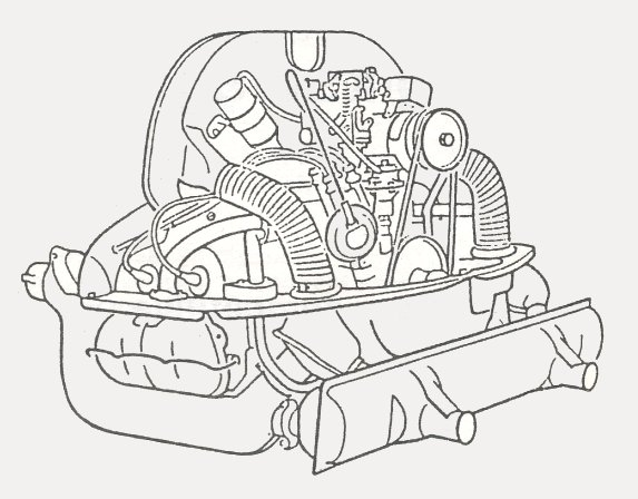
The first people to enjoy what the VW had to offer were more than content with however little it may have seemed. It was not meant as a performance car, after all; more to the point was its existence than its performance. So could it do better than 100 km/h? It could do that all day, loping along in a very high gear that ensured decent fuel economy. Designed at a time when low piston speeds were being touted as the key to reliability, the engine naturally had a short stroke. But the large bore that complemented it was not exploited to allow large valve and port areas for high speed breathing. On the contrary, the ports were deliberately kept tiny, the breathing constricted so that the engine simply could not ingest enough air to develop high power or run at high revs. Peak power, a humble 25 bhp in the original 1131cc engine, was given at a trifling 3300 rpm, and the built-in asthma stopped rpm rising beyond 4000 in almost any situation. Other engines of its time were governed by valve float so they could not be over-speeded, but it was a brutal method. In the VW engine, valve float occurred at 5500rpm, but the only way to reach that rate was to drive at full throttle down an exceptionally steep hill in bottom gear !
Air-cooling was seen as another aid to reliability, and in the hot and arid places of the world (north Africa, USA, Australia) it proved effective. Following excellent examples set in Czechoslovakia and Austria, the air-cooled engine was designed to maintain its shape whether hot or cold. Cylinder barrels were independent of each other so that their thermal expansion could be symmetrical about their axes, and they were merely bridged by the twin cylinder heads. An early modification splayed the valves slightly to improve airflow between them, and a little later there was a thermostat to throttle the cooling airflow introduced by the engine-driven fan so that the engine should not be overcooled when running light.
It was alleged that air-cooling makes the engine inevitably noisy, because of sound radiated by the cooling fins. Volkswagen may have accepted this view, but it was not strictly true. Researchers in Prague once machined the fins off an air-cooled diesel cylinder and water-jacketed it; the measured sound output was unchanged. NSU filled the gaps between the fins of one of their engines with concrete, then ran it for the brief time required for noise measurements before the concrete-lagged cylinder would overheat; once again, there was no change in the measured sound output. It was the fan that made the noise, especially when (as in the VW) it induced airflow through a cowling contoured to guide the cool air between the fins.
Even on the horrid low-grade petrol of the times, which imposed a compression ratio of only 5.8 to one, there was no risk of the VW overheating at a continuous rating of 25 bhp. The time came, however, when the needs of the people grew more expansive, when performance standards had risen so much since the car was originally designed (two decades earlier), that its feeble acceleration was a handicap, even if its excellent traction still made it a respectable hill climber.
From 1954 onwards, the engine was progressively uprated; but improvements that might or might not pave the way for such performance improvements were made steadily and frequently from 1949. That was when the mating transmission case was made of Elektron magnesium alloy, as the crankcase was to be two years later.
Balancing of the clutch, flywheel and crankshaft assembly followed in 1953, and with changes to valve springs, valves and distributor, everything was ready for a bore increase which enlarged the displacement to 1192cc. Up went the compression ratio to 6.6 to one, the peak power rpm to 3700, and the power output to 36 bhp. In the next six years there were only detail changes (an alloy timing gear instead of fibre to drive the camshaft, for instance) until it was time to redesign the crank, spread the cylinders apart a bit, and boost the power to a hairy 40 bhp. At the time it was reckoned a pretty sensational development, accompanied as it was by a new gearbox with syncromesh on all four ratios.
Never mind all the changes that followed. They are too many and too boring to list, just like the many others that send enthusiasts into raptures. There are far more important things about the VW engine. The fact that it was a flat four was one of them, proving that logic was employed where it mattered; four cylinders was the least that could secure acceptably smooth running with perfect primary and secondary balance. It also served to keep the weight low (thanks to those costly light alloys), and to give the cylinders cooling draughts.
The fact that it had overhead valves was another. Rivals would have chosen side valves for anything meant to be so modest in output and rotational speed, so cheap and universal in appeal, so easy to maintain and overhaul. In Germany the desire for efficiency grew into a burning need, with fuel scarce and expensive, and the opportunity to maintain top speed for an hour or two on the autobahnen something worth exploiting. An overhead valve engine was more efficient in every way. At long overdue last, it was being demonstrated that the best way to make a truly efficient touring engine was to design a detuned racing engine.
In those days a chain was not good enough, gear trains not quiet or precise or cheap enough, and cogged belts not yet invented; otherwise the VW would have been an overhead camshaft job, just to make the lesson complete.
A Long Life For Air-Cooled Engines
By Simon Glen
December 2001
Warm Up
All VW engines need to be warmed up gently, especially if they have been standing overnight. Moreover, air-cooled engines do not have a water jacket to promote even and rapid warm up to operating temperature. So, allow your motor to idle for at least a couple of minutes before driving off. Even then, drive off gently. Do not subject the engine to high revs and heavy loads when still cold. To roar off down the road in a hurry to get to work in the morning is one of the fastest ways to a premature engine rebuild.
Cool Down
If you have been driving hard and fast on the open road and then stop, do not switch off your engine straight away. Allow it to idle for at least 2 or 3 minutes. Unlike water-cooled motors, air-cooled motors run coolest at idle. If a hot air-cooled motor is allowed to idle, it will steadily come down in temperature at its own pace. Switching off a hot air-cooled engine will have the opposite effect. Stationary hot air around the motor and hot oil inside the motor will actually cause the engine temperature to increase before it cools. So, on that trip to Nambucca Heads, when you pull into Burger King at Hexham after the fast run up the freeway, let the engine idle for a few minutes before switching off. Your motor will thank you for your courtesy with a longer life.
Gear Changes
Do not allow the engine to labour in a high gear going up a hill or when pulling a load. This places undue stress on the crankshaft. Likewise, do not forget to change up into a top gear once you've reached the top of a hill. Remaining in a low gear at high speed may cause overheating, early valve failure and excessive noise.

Check Tappets, Timing, Contact Breaker Points and Spark Plugs
Tappets or valve clearances should be checked and, if necessary, adjusted every 3,000 km. This will promote long valve and valve guide life. It may also let you know when something is going wrong with a valve before it causes major damage. Of course, if your VW has hydraulic tappets the valves should look after themselves.
Timing and points should be checked every 3,000km at the same time as the tappets to ensure that your motor does not overheat or unduly stress itself, or use too much fuel. For the same reasons, fit new spark plugs every 15,000 km.
Oil Changes
Change engine oil every 5,000 km and the oil filter (if your motor has one—if not, seriously think about fitting one) every 10,000 km at least. Better still, be generous and change oil AND filter every 5,000 km. The extra expense is small insurance. Doing a lubrication service more often can only benefit your motor.
Air Cleaner
Make sure your air cleaner is clean and operating effectively. Not to do so will allow dust into the combustion chamber and cause rapid valve and piston ring wear.
Engine Lid
Beetles can benefit from rear engine lid standoffs, which leave a gap at the top of the engine lid to allow more cooling air into the engine bay. However, with Kombis do NOT drive with the rear engine lid open. This sucks in both dust and hot air, which has already been expelled by your motor. It does not promote cooler operating.
Oil Leaks
A leaky air-cooled engine runs hotter. Oil spread around an engine's cooling fins reduces their ability to transmit heat into the air. It also attracts dust which cakes itself around the cooling fins, reducing the cooling process even more. Frequently check the back of the vehicle (such as the engine lid) for spots of oil thrown up into the airflow vacuum at the rear. This is the quickest and simplest way to see the degree to which your engine is leaking.
And Finally...
Keep Your Motor Standard !!
How Turbochargers work
by Karim Nice
April 2002
When people talk about race cars or high-performance sports cars, the topic of turbochargers usually comes up. Turbochargers also appear on large diesel engines. A turbo can significantly boost an engine's horsepower without significantly increasing its weight, which is the huge benefit that makes turbos so popular.
Turbochargers are a type of forced induction system. They compress the air flowing into the engine. The advantage of compressing the air is that it lets the engine squeeze more air into a cylinder, and more air means that more fuel can be added. Therefore, you get more power from each explosion in each cylinder. A turbocharged engine produces more power overall than the same engine without the charging. This can significantly improve the power-to-weight ratio for the engine.
In order to achieve this boost, the turbocharger uses the exhaust flow from the engine to spin a turbine, which in turn spins an air pump. The turbine in the turbocharger spins at speeds of up to 150,000 rotations per minute (rpm) — that's about 30 times faster than most car engines can go. And since it is hooked up to the exhaust, the temperatures in the turbine are also very high.
One of the surest ways to get more power out of an engine is to increase the amount of air and fuel that it can burn. One way to do this is to add cylinders or make the current cylinders bigger. Sometimes these changes may not be feasible - a turbo can be a simpler, more compact way to add power, especially for an aftermarket accessory.
Turbochargers allow an engine to burn more fuel and air by packing more into the existing cylinders. The typical boost provided by a turbocharger is 0.4 to 0.6 bar. Since normal atmospheric pressure is 1 bar (101.3 hPa) at sea level, you can see that you are getting about 50 percent more air into the engine. Therefore, you would expect to get 50 percent more power. Of course it’s not perfectly efficient, so you might get a 30- to 40-percent improvement instead.
One cause of the inefficiency comes from the fact that the power to spin the turbine is not free. Having a turbine in the exhaust flow increases the restriction in the exhaust. This means that on the exhaust stroke, the engine has to push against a higher back-pressure. This subtracts a little bit of power from the cylinders that are firing at the same time.
The turbocharger also helps at high altitudes, where the air is less dense. Normal engines will experience reduced power at high altitudes because for each stroke of the piston, the engine will get a smaller mass of air. A turbocharged engine may also have reduced power, but the reduction will be less dramatic because the thinner air is easier for the turbocharger to pump.
Older cars with carburettors automatically increase the fuel rate to match the increased airflow going into the cylinders. Modern cars with fuel injection will also do this to a point.
If a turbocharger with too much boost is added to a fuel-injected car, the system may not provide enough fuel — either the software programmed into the controller will not allow it, or the pump and injectors are not capable of supplying it. In this case, other modifications will have to be made to get the maximum benefit from the turbocharger.

The turbocharger is bolted to the exhaust manifold of the engine. The exhaust from the cylinders spins the turbine. The turbine is connected by a shaft to the compressor, which is located between the air filter and the intake manifold. The compressor pressurizes the air going into the cylinders.
The exhaust from the cylinders passes through the turbine blades, causing the turbine to spin. The more exhaust that goes through the blades, the faster they spin.
On the other end of the shaft that the turbine is attached to, the compressor pumps air into the cylinders. The compressor is a type of centrifugal pump — it draws air in at the centre of its blades and flings it outward as it spins.
In order to handle speeds of up to 150,000 rpm, the turbine shaft has to be supported very carefully. Most bearings would explode at speeds like this, so most turbochargers use a fluid bearing. This type of bearing supports the shaft on a thin layer of oil that is constantly pumped around the shaft. This serves two purposes: It cools the shaft and some of the other turbocharger parts, and it allows the shaft to spin without much friction.
There are many tradeoffs involved in designing a turbocharger for an engine. But before we talk about the design tradeoffs, we need to talk about a some of the possible problems with turbochargers that the designers must take into account.
With air being pumped into the cylinders under pressure by the turbocharger, and then being further compressed by the piston, there is more danger of pre-ignition (‘knock’). Knocking happens because as you compress air, the temperature of the air increases. The temperature may increase enough to ignite the fuel before the spark plug fires. Cars with turbochargers often need to run on higher octane fuel to avoid knock. In practice the compression ratio of the engine is usually reduced to avoid knocking.
One of the main problems with turbochargers is that they do not provide an immediate power boost when you step on the gas. It takes a second for the turbine to get up to speed before boost is produced. This results in a feeling of lag when you step on the gas, and then the car lunges ahead when the turbo gets moving.
One way to decrease turbo lag is to reduce the inertia of the rotating parts, mainly by reducing their weight. This allows the turbine and compressor to accelerate quickly, and start providing boost earlier.
One sure way to reduce the inertia of the turbine and compressor is to make the turbocharger smaller. A small turbocharger will provide boost more quickly and at lower engine speeds, but may not be able to provide much boost at higher engine speeds when a really large volume of air is going into the engine. It is also in danger of spinning too quickly at higher engine speeds, when lots of exhaust is passing through the turbine.
A large turbocharger can provide lots of boost at high engine speeds, but may have bad turbo lag because of how long it takes to accelerate its heavier turbine and compressor. More sophisticated racing engines such as Le Mans Porsches often use twin turbochargers to get both high boost and quick spool-up.
Most automotive turbochargers have a wastegate, which allows the use of a smaller turbocharger to reduce lag while preventing it from spinning too quickly at high engine speeds. The wastegate is a valve that allows the exhaust to bypass the turbine blades. The wastegate senses the boost pressure. If the pressure gets too high, it could be an indicator that the turbine is spinning too quickly, so the wastegate bypasses some of the exhaust around the turbine blades, allowing the blades to slow down. In racing Porsches, the wastegate can be manually varied to ‘turn up the boost’ when needed.
Some turbochargers use ball bearings instead of fluid bearings to support the turbine shaft. But these are not your regular ball bearings — they are super-precise bearings made of advanced materials to handle the speeds and temperatures of the turbocharger. They allow the turbine shaft to spin with less friction than the fluid bearings used in most turbochargers. They also allow a slightly smaller, lighter shaft to be used. This helps the turbocharger accelerate more quickly, further reducing turbo lag. Of course they cost a packet and you’ll only see them on high-end race cars.
Ceramic turbine blades are lighter than the steel blades used in most turbochargers. Again, this allows the turbine to spin up to speed faster, which reduces turbo lag.
Some engines use two turbochargers of different sizes. The smaller one spins up to speed very quickly, reducing lag, while the bigger one takes over at higher engine speeds to provide more boost.
When air is compressed, it heats up; and when air heats up, it expands. So some of the pressure increase from a turbocharger is the result of heating the air before it goes into the engine. In order to increase the power of the engine, the goal is to get more air molecules into the cylinder, not necessarily more air pressure.
An intercooler, or charge air cooler, is an additional component that looks something like a radiator, except air passes through the inside as well as the outside of the intercooler. The intake air passes through sealed passageways inside the cooler, while cooler air from outside is blown across fins by the engine cooling fan.
The intercooler further increases the power of the engine by cooling the pressurized air coming out of the compressor before it goes into the engine. This means that if the turbocharger is operating at a boost of 0.5 bar, the intercooled system will put in 0.5 bar of cooler air, which is denser and contains more air molecules than warmer air.
Turbocharging is a worthwhile way of increasing the efficiency and power output of engines.
Performance Volkswagen summary
By Mike McCarthy (Wheels magazine, 1963)
May 2003
The Volkswagen just had to be a success, if only because it seems to be an exception to more rules than any other car. This particularly applies when it comes to hotting-up the engine.
Almost anyone with a reasonable amount of mechanical knowledge can modify engines such as the Morris, Holden and Ford, but a VW hot-up requires specialised treatment if it is to be effective.
There are, of course, a number of twin carburettor installations available, and fitting one of these is about the limit for amateur tuners. The two most popular kits use Solex or SU carburettors. The Solex kit usually consists of two stub inlet manifolds (either cast or fabricated), plus fuel lines, accelerator linkages, balance pipe, etc. In this form the cost is approximately £15 ($30). Because the existing carburettor is used, the owner has only to supply another identical unit and air cleaner to complete the assembly.
A point worth noting, however, is that the older type carburettor (from the 36-bhp model) with its manually operated choke gives better results than the later automatic choke variety. Superior performance is obtained with the manual choke instruments, rather than the auto choke version. One of each type should NOT be fitted.
An alternative is to fit SU carburettors. The basic hardware in these kits is much the same as in those for the Solex, but two 1 1/8 in or 1 ¼ in SU carburettors are furnished together with suitable air cleaners. Typical packages are priced at about £45 ($90) complete.
Little else can be done to the Volkswagen without removing the engine, except to fit a non-restrictive exhaust system. Incidentally, apart from increasing the noise level nothing substantial performance wise is gained by removing the existing muffler's tailpipes. The design is such that the pressure is built up internally, and dispensing with the tailpipes will not relieve it appreciably.
Lukey mufflers are among the best available for Volkswagen. They are claimed to improve a standard car's 0 to 110 km/h acceleration time by up to seven seconds, yet improve fuel consumption by a litre or more per 100 km. There are three types, the main differences being in the outlet pipe arrangement. There is a twin-piper with 1¾ in outlets, and twin and four pipers with 1¼ in outlets. All retail at about £8.15.0. ($16.30) For optimum results Lukey advises ignition advancement and carburettor main jet replacement.
Now, to the more advanced stages of hotting-up. We will not take on supercharging as well because we haven't the space to discuss the subject fully. There are suitable blower kits available and outstanding results can be obtained from a good installation. If it's supercharging you favour we can only recommend you first get the pros and cons of the matter from someone who has had firsthand experience. Incorrectly pressurised VWs are notoriously susceptible to melting pistons!

Unlike most engines, which can be fairly well reworked while in the car, the VW's has to be removed holus-bolus if anything more than a port and polish job is undertaken. The task of engine removal and dismantling calls for fairly specialised knowledge and equipment. It is, therefore, beyond the scope of the average home mechanic.
For this reason we went out to Jay Bee Motors (They were in Planthurst Rd Carlton in southern Sydney - Ed) and had the whole hot-up procedure clarified by VW and Porsche specialist Jack Bono.
The first thing that can be put on the bill is the cost of removing, stripping, reassembling and reinstalling the engine/transmission. This costs £36 ($72), not including labour and parts the actual hot up may involve. To keep things on a level footing, Jack carries out modifications on a you-supply-the-components basis, although some items are available on an exchange system.
What could be termed stage one is to increase the capacity to 1300 cc at a cost of £36 ($72). This entails boring out the cylinder barrels to 80 mm and fitting appropriate pistons and rings. The over bore raises the compression ratio to 7.7 to 1. This gives a worthwhile 18 per cent increase in bhp and torque. Also included in the process are modifications to the connecting rods in which the little ends are bored out to accept larger diameter gudgeon pins.
Apart from increasing the power, the over bore is beneficial for another reason. With the cylinder wall thickness reduced the engine's heat is transferred to the cooling fins much more readily and the operating temperature becomes more stable.
Next in line is a modified camshaft. This can be supplied on an exchange basis with a choice of two grinds to give either standard Porsche timing, or the hotter Porsche Super timing. Cost is £7.15.0. ($14.30)
Following that the cylinder heads are reworked. In case there are doubts as to why the heads are left alone to this point, well here’s why. The stock VW engine is very much de tuned in the interests of durability. This makes it imperative that no great single hot-up step should be taken without regard to other factors. Naturally, it would be possible to thoroughly modify the cylinder heads to improve the breathing without otherwise touching the engine's internals. But better breathing would mean more power and more unwanted heat. Similarly, because of the standard engine's mild valve tinning, the full benefit of the cylinder head modifications would not be realised. After all, there's not much point in having an unrestricted inlet tract if the inlet valve opens too late and closes too early to let a much greater charge be drawn in.
A twin carburettor kit improves the VW's acceleration, but does not greatly improve top speed. Manifold and linkages cost £15 ($30).
The usual porting and polishing routine to promote deeper breathing can be usefully aided by fitting larger diameter inlet valves. New inserts have to be installed, as the originals cannot cope with much of an increase. To a 36-bhp engine Jack fits inlet valves that are three millimetres larger than stock, while the 40-bhp model will take- an increase of up to five and a half millimetres. The stellited valves cost £2 ($4) each, while the entire modification (including fitting the new inserts) is approximately £24 ($48).
Up to this stage the induction will be handled quite satisfactorily by either of the twin carb arrangements mentioned previously. Should larger carburettors be required it becomes necessary to extensively modify the inlet system. This involves removing part of the existing inlet passage (which is integral with the head), filling the outer end of the passage, and boring a new port in from the side (which is upper most), thereby obtaining a much shorter route than normal. The charges for relocating the inlet ports by this method vary depending on what is required, but it is not cheap.
That covers all that can be done with the basic engine - increased bore, raised compression, modified camshaft and improved breathing. All these apply equally to the 36 and 40-bhp engines. The 40-bhp model, though, has an inherent restriction because its distributor relies solely upon vacuum to operate the advance/ retard mechanism, undesirable with twin carbs. Correct ignition timing can be obtained by fitting the older model distributor, which has both vacuum and centrifugal controls. Even then Jack Bono eliminates the vacuum system and relies on the weights alone.
Another £2.10.0 ($4.20) can be wisely spent by having four extra dowels added to the crankshaft stub as a precaution against loosening of the flywheel. And it's also a safety measure to remove the throttle ring from the cooling shroud to allow maximum airflow at high engine revs.
Upping the VW's power substantially spells doom to the standard clutch assembly. Fitting the pressure plate from a VW Kombi can prevent slippage and eventual failure.
All things being equal, however, it is either the Okrasa or the Denzel conversion kits that attract the serious Volkawagener. They put a tiger in the boot. The Denzel kit, selling at £350 ($700) including tax, is the more expensive and comprehensive. It is designed specifically for the 36-bhp engine, which literally becomes a Denzel. Apart from the crankcase, camshaft and oil pump, few original components are retained. The kit comprises of two alloy cylinder heads (with separate ports, large valves, double valve springs) four alloy cylinder barrels with hard chrome liners, a full circle stroker crankshaft (nitrided) with increased diameter connecting rod journals (Porsche size), high compression pistons, heavy duty connecting rods, two 32 mm Solex carburettors and manifolds, plus long reach spark plugs, all linkages, fuel lines, an oil filter and engine shroud plates.
A completely equipped VW/Denzel has bores of 78 mm and a stroke of 67 mm, giving 8.2 to 1 compression ratio and 1281 cc capacity. With the stock VW camshaft 64 bhp is developed at 4700 rpm, but fitting an alternative hot cam raises the output to 72 bhp at 5400 rpm!
Some of the components can be bought individually. For instance, the Denzel crankshaft and rods, together with suitable pistons, can be fitted to an engine, which has been over-bored to 80 mm (taking the compression to 8 to 1 and the capacity to 1340 cc) for £146 ($292). Or the Denzel crankshaft and rods can be bought for £112 ($224).
At the moment only the TSV-1300 Okrasa kit can be supplied ex stock. This fits either the 36 or 40-bhp engines. Retailing at £248 ($496) the Okrasa conversion is based on a pair of alloy cylinder heads, a stroker crankshaft and twin carbs. (A new Deluxe Beetle was £849 [$1698] when this article was written - Ed). The crank has a stroke of 69.5 mm, giving the engine a capacity of 1295 cc when used in conjunction with the standard bore. The compression ratio with stock Okrasa heads is 7.5 to 1, but heads giving 8 to 1 may be ordered. With a standard camshaft and the lower compression ratio, a 1300 Okrasa VW develops 54 bhp at 4200 rpm.
The TS/34 Okrasa kit has not yet reached this country, although it is due soon. It includes the same type of cylinder heads and carburetion set-up as its companion kit, but the special crankshaft is omitted.
Finally, getting the Beetle to handle. This boils down to nothing more or less than reducing the oversteer characteristic for the betterment of roadholding. An improvement can be made by fitting a stabiliser bar to the front suspension if the vehicle is not so equipped. You can use either a Volkswagen spare part as fitted to the later models, or one of the proprietary components which are usually slightly stiffer than the factory built item.
But there's no getting away from the fact that the rear suspension must be modified for best results. The greatest reward lies in fitting a Porsche-type compensating spring to the rear suspension. Since the primary abject is to decrease rear roll resistance, the rear torsion bars need resetting so the wheels assume three degrees of negative camber. The amount may be more or less, depending on the work the car does and the normal load it carries.
In this position the car has a distinct droop at its tail, but this is counteracted by fitting the compensating spring and loading it (by adjusting its shackles) to bring the wheels back to vertical or slightly positive camber. The effect, when the car is travelling straight ahead, is that the suspension acts in the normal way, but when it enters a corner the outside rear wheel tucks well up, with plenty of negative camber, because the torsion bars restrain it to a lesser amount.
If this is confusing, imagine that the torsion bars were disconnected altogether and the compensating leaf spring was beefed up to carry the full load. If you were to jump on the rear bumper the car would bounce as though normally sprung. However, if you pushed on the car's side it would tilt over, restrained only by the front suspension's resistance. This is due to the leaf spring not being mounted directly to the sprung mass, it simply bears against the underneath of the transmission casing.
Of course, this would be too extreme to be practical, so a moderated effect is obtained by softening the torsion bars. That is the crux of the business, having normal spring resistance when travelling ahead, but less resistance to roll when subjected to side forces. The required effect cannot be obtained by merely fitting the compensating spring, for the torsion bars have to be reset in order to allow the body to roll more freely.
Another chassis-tuning modification from Jack Bono is to reverse the shock absorbers, those from the front suspension to the rear and vice-versa. Widening the rear track will also make the VW more secure because the roll centre is lowered slightly. This can be done at reasonable cost and with maximum safety by having the wheel rims ground from their centres, then re-welded about half an inch further out. It is a dangerous practice reversing the wheels by turning them inside out. The wheel centre will bear against the drum only at a thin strip around the studs.
Volkswagen's VR6 engine explained
By Anthony Dennis
November 2003
6-cylinder engines, no matter in vee-shape or arranged inline, have superior smoothness against an inline 4-cylinder because all the first order and second order forces can be balanced. However, for most small cars, they don't have the space to accommodate 6-cylinder engines. For space efficiency reason, nearly all-small cars employ front engine-front-wheel-drive configuration; that is, ‘FF’. The engine, clutch, gearbox and differential are all installed up front, accompanied with ABS pump, servo, air-conditioning, battery and steering mechanism etc. Therefore it is not easy to fit a six-cylinder engine into the car, especially a straight six, which is too long for FF because the gearbox and clutch has to be installed right beside it. Even the big Volvo S80 has to specially develop a compact gearbox. A V6 could be better because it is very much shorter; at least it can be fitted to Rover 400.
Undoubtedly, engines for small cars have to be mounted transversely, unless it is BMW 3-series Compact, which has a long long bonnet (hence poor space efficiency). But even mounting transversely can't guarantee the installation of a V6. The width of V6 (excluding accessory) is at least doubled from inline-six, depending on the incline angle (usually 60° or 90°), so it uses a lot of length of the engine compartment. Moreover, the hot exhaust pipes in either side of the Vee also prevent any other components from placing too near, thus needing more clearance. Therefore most small cars cannot accommodate a V6.
In 1991, a breakthrough was achieved by Volkswagen. VW developed a narrow-angle (15°) V6 displacing as much as 2.8 litres, and installed it to the 3rd generation Golf. As everybody knows, this is the so-called ‘VR6’, which is short for ‘Vee Reihenmotor’ six (‘Vee Row, or Vee Straight). The VR6 is really very compact, nearly as narrow as any inline engine and not much longer than a straight four. It could be fitted to many small cars, including Polo (which didn't because of price reasons). It is also supplied to the Mercedes-Benz V-class, whose short front end cannot fit Mercedes' own V6.
The reason the VR6 could be as narrow as 15° without cylinders overlapping is because adjacent cylinders are widely spaced from each other. Imagine a normal V6, with two banks of three cylinders each. Now bring the vee angle in, and spread the cylinders in each bank apart. You end up with an almost ‘in-line’ six, but with the cylinders alternating left, right, left, right, left, right. This arrangement does increase the length over an in-line four, but it’s shorter than an in-line six. In fact its length is equal to four and a half cylinders, thanks to the alternating left-right. For most small cars this is short enough.

A further comparison between a straight-4, V6 and a VR6's cylinder block, viewing from above, shows the VR6 is a lot narrower than a normal V6, and only slightly wider than an in-line engine. This makes it ideal for today’s transverse front-drive installations.
Another feature of the VR6 is very important - the VR6 is asymmetric. For a conventional V6, one bank of cylinders mirrors another bank exactly. That is, air and fuel intake comes from the centre of the vee (V6 and V8 engines always have a centre manifold), while the exhaust comes out from outside of the vee, with the pipes heading off from both sides.
The VR6, on the other hand, is like an in-line engine. It has the air/fuel intake from one side only, and the exhaust from the other side for ALL cylinders, so it is not a symmetric design. This has an additional space benefit. On a normal V6, there are two exhaust manifolds, one on each side, and that takes up a lot of space (or length) of the car, especially is a certain clearance should be provided to avoid overheating to surrounding components. The VR6 concentrate all the exhaust pipes to one side of the engine, like an in-line four, thus save space.
The first generation VR6 had two valves per cylinder and a single overhead camshaft (SOHC) serving each bank, just like any conventional two-valve V6, although the two camshafts are so close that they look like a twin-cam design.
In many ways the VR6 is constructed like an in-line engine. Thanks to the narrow angle, the two banks are merged into a single cylinder block. A single cylinder head covers both banks (there is no ‘space’ in between), and houses the valve gears for all six cylinders. In contrast, a conventional V6 consists of two banks and two heads. As a result, VR6 is not only smaller, but also lighter. It would have been cheaper as well, if not needing to employ a seven-bearing crankshaft.
While the rest of the automotive industry world was focusing on 4-valve per cylinder engines, Volkswagen's VR engine (both VR6 and V5) still relied on the first SOHC 2-valve head until the arrival of the second generation VR6 in July 1999. You may wonder why it took eight years to bring the VR6 a 4-valve head. In fact, there was a very big technical difficulty behind the development.
When I first heard the rumour about the 24V VR6 in 1997, the first question arose in my mind was: how do you fit four camshafts into the ‘in-line cylinder head? It is virtually impossible, especially when some space has to be preserved for replacing spark plugs. Well if you can’t have four camshafts, then it must be an SOHC design serving four valves per cylinder, which is already done on many Japanese cars such as Honda and Mitsubishi.
However, SOHC 4-valve is not a perfect design. Firstly, it concentrates 3 or 4 elegant, narrow cams to every cylinder, and is thus relatively complex. Secondly, the most ideal position of a rocker arm / cam set is exactly vertical above the valve it controls. Otherwise the arrangement may generate a lateral movement, which wastes power and introduces friction. Because the ideal position of the rocker arms for intake and exhaust are exactly the same on a SOHC four, a small distance shift must be introduced to one or both of them, resulting in the aforementioned drawback. In fact, all the high performance Hondas employed DOHC instead of the SOHC for just this reason.
But the most important reason that the SOHC 4-valve is not desirable is that it doesn't allow the adoption of cam-phasing variable valve timing. Shift the camshaft 20° in advance leads to the intake valves opening and closing earlier, but so do the exhaust valves. Therefore there is no gain in performance.
Using cam-changing VVT like VTEC or MIVEC may introduce real performance gains, but it doesn't improve drivability at low speeds and thus European car makers are not very interested in it. How did Volkswagen overcome these difficulties?
Volkswagen’s ingenious engineers solved the problems by introducing a revolutionary concept: Twin-camshaft per bank, one for intake, one for exhaust, but also totalling just two camshafts altogether. Yes, sometimes 2 x 2 = 2.
This is how it works. Remember that the VR6 has two banks of three cylinders, but so close together (just 15 degrees apart), that it is really an in-line engine with the cylinder centre-lines alternating left-right. Above the centre of each ‘bank’ is one camshaft, meaning the head has just two camshafts altogether.
Now here’s the trick. One camshaft controls the intake valves for BOTH banks, while the other camshaft controls the exhaust vales for BOTH banks.
Now it is clear. Camshaft A controls the intake valves of bank A as well as bank B. Similarly, camshaft B controls the exhaust valves in bank B and bank A. In other words, every cylinder is served by both camshafts, and hence it is a ‘twin-cam’ engine.
If you still remember, a feature of VR6 is that it is asymmetric, and this enables the exhaust valves in both bank to remain at a distance accessible by a common camshaft. In fact, the distance is the same as in intake valves / cam set. This ensures equal efficiency of intake and exhaust. Without the narrow angle and the asymmetric configuration, the share of camshaft would have been impossible.
Such design allows cam-phasing variable valve timing to be installed. In the 24-valves VR6, the intake camshaft has VVT. In the future, the exhaust camshaft may also introduce VVT, just like BMW's Double Vanos. If it were a conventional V6, it would have needed 4 camshafts and a 4 cam-phasing mechanism to implement this. Also required are 2 cylinder banks and 2 cylinder heads. The VR6 needs just half of them.
It is also interesting to see the new VR6 has the same number of camshaft as its 2-valve predecessor. It is one of the most remarkable inventions.
Having learned the VR6, it is not difficult to understand the W12, used only in the VW Phaeton, the VW Touareg and in some Bentleys. The W12 engine is basically a combination of two VR6s. This is confirmed by its 5.6-litre displacement. It is constructed by mating two 15° VR6 in an inclined angle of 72°. In fact it was the first VR engine to have the 4-valves head, although the W12 ‘supercar’ concept was never put into production.
The W configuration would have been never realised if not the invention of VR6. Audi had been researching its own W-engines for years, and even showed it in the Avus concept car (with a mockup engine), but eventually pulled out the plug. It failed to solve the exhaust / ventilation problems. It was a different layout from the VW W12. Instead of four banks of three, the Audi engine had three banks of four in-line cylinders, with an upright bank in-between the vee. It was just like the pre-war Napier Lion aeroplane engine in layout. Audi’s problem was how to run the exhaust pipe for the centre bank without overheating the surrounding and without wasting too much space, one they never solved.
It seems that Volkswagen's approach wasn’t benefited by Audi's experience, because the Volkswagen unit is based on the VR6, which was under development well in the 1980s. Benefited by VR6's asymmetric design, exhaust of the left VR6 runs out from the left side, while exhaust of the right VR6 runs out from the right side. Therefore the exhaust system is just the same as any Vee engine.
The only shortcoming of W-engines is that they require very thin connecting rods, as the crankshaft is much shorter than V-engines. While VR6 uses con-rods with 20mm thickness, the W-engines run with 13mm ones. This prevents it from becoming racing engines, and cylinder heads may also limit its breathing and ventilation.
Similar to the W12, the Bugatti Veyron’s W16 is made by mating two VR8s together, although at the moment Volkswagen group has not shown any VR8 on its own. The VR8 consists of 2 banks of 4-cylinder, mated at 15° just like VR6. The two VR8s then join together at 72°. In other words, the W16 is just a W12 with one more cylinder added to each bank.
The W8 engine was first introduced in Volkswagen Passat W8. As it is produced in the same production line of other modular family members, the basic architecture is the same as W12 and W16. In other words, it is a W12 with 1 cylinder deleted from each bank, or simply one half of a W16. The Passat’s W8 consists of a pair of 15° VR4 engines, joined to a common crankshaft at 72°.
Recently Volkswagen revealed the Bugatti EB-218 concept car. It featured a ‘W-18’ engine. But hang on – you can’t divide 18 by four. Therfore we know that the W-18 can’t be derived from VR engines, like the W12 and W16.
In fact, this one follows the old Audi / Napier Lion philosophy of mating 3 banks of 6-cylinders together, running on a common crankshaft. The drawback is the 60° angle between each bank, meaning an angle of 120° between the two outer banks. For comparison, the W16 is just 15/2 + 72 + 15/2 = 87°. Therefore the W-18 is a lot wider. In terms of length, the W16 has the same length as a VR8, that is, about the length of 5 cylinders. The W-18 is as long as an inline-6.
The W-18 engine used by Bugatti EB-218 concept car is very big and complex. Two of the banks mate like a conventional 60° V6 while the remaining bank lies down to horizontal level. Complex induction manifolds and exhaust pipes run between the banks. (Note that the exhaust pipes were not fitted to this prototype, otherwise it would have looked even more complex.) Obviously, W-18 is not as clever as W-16. Although there is no problem of fitting it in the jumbo Bugatti saloon, I must question its purpose. Is it more powerful than a V12 can achieve? No. Is it smoother than the theoretically ideal V12? No. Is it shorter than a V12? No. Is it narrower than a V12? On the contrary. Is it cheaper to be built? Never.
No wonder Volkswagen eventually decided to terminate this project.
Volkswagen TDI Diesels
By Karl Jansen
September 2004
We all know diesel engines, right? Loud, smoky, slow and pains to start? Wrong. That may be where they've came from, but thanks to the advent of TDI (Turbo Direct Injection), they're set to become the smooth, economical, high performance engines of the future.
Pioneered by Volkswagen's performance lab and VW’s daughter Audi in 1989, TDI not only put diesel engines on a par with spark-ignition systems (petrol) for power and performance, it eclipsed them in terms of torque. The basic principle involves a turbocharger forcing an optimal amount of fresh air into the cylinder, then, directly after the compression stroke, an injector delivers diesel fuel at very high pressure directly into the compression chamber.
Direct injection allows better, more complete combustion, which increases efficiency and reduces emissions. This has made TDI synonymous with power, high performance and low fuel consumption. The addition of more effective engine encapsulation and hydraulic engine mounts has in addition reduced noise and provided smooth running and low vibrations.

What Volkswagen have done is to refine this excellent principle even further by adding highly advanced ‘Pump Nozzle’ injection systems, which allow higher injection pressures. Here, each cylinder is fitted with a pump-nozzle unit that combines an injection pump with a controller and injection nozzle. The units build up high injection pressure (currently 2,050 bar) mechanically via an additional cam connected to a small, high-speed plunger. The plunger, controlled by a solenoid valve, pumps rapidly, which quickly builds up pressure in the so-called ‘plunger chamber.’ When the solenoid valve closes, the pressure build up stops (vital for complete and clean combustion) and the pressure is exerted to inject fuel.
The pump-nozzle system provides the highest injection pressure for more efficient combustion.
These units are capable of producing much higher injection pressures than other diesel injection systems (28% more than the latest common rail injector), and deliver balanced injection, improved torque, reduced emissions, silky smooth running of the engine and up to 45%greater fuel efficiency. The current pinnacle of VW’s diesel development work is the V10 TDI. Built around 10 cylinders in a Vee configuration (something more typical of a Formula 1 race car), this awesome power plant delivers some incredible stats:
• 230kW at 4,000rpm
• 750Nm of torque from just 2,000rpm
So incredible in fact that in 2003 it won the prestigious International Engine of The Year Award in the above-4.0 litre category.
Presently, the V10 is only available in Australia on the Touareg where it translates into 0-100 km/h in 7.8 sec, 225 km/h top speed and a combined fuel economy of just 12.3 litres per 100km.
You needn't however, drive top of the range to enjoy TDI diesel excellence. The 5 cylinder, R5 engine now available on the Touareg, as well as the 1.9 and 2.0 L diesel power plants on the Golf V all feature TDI direct injection and deliver the exact same enhanced torque, improved fuel efficiency, smooth running and reduced emissions as the award winning V10.
Volkswagen FSI Technology
By Hans Schrader
September 2004
Volkswagen’s FSI, or Fuel Stratified Injection, represents the state-of-the-art in fuel injection technology. It increases both torque and power of spark-ignition engines, while improving economy (up to 15%) and reducing exhaust emissions. As opposed to standard manifold injection systems, FSI engines inject fuel directly into the cylinder and use a specially shaped piston crown to concentrate the air/fuel mix below the sparkplug. They also dispense with the throttle plate, effectively 'un-throttling' the engine. This combination of factors produces optimal fuel combustion and reduces heat loss, which increases output while reducing fuel consumption and emissions. In ‘on road’ terms this equals more power from less fuel: a result that's better for drivers as well as the environment.
VW FSI functions in two modes: stratified charge (partial loading) and homogeneous operation (full loading). When the vehicle is not under full loading, such as coasting or cruising on almost no throttle, the stratified charge mode kicks in reduce fuel consumption to a minimum without affecting performance. It functions via a 'charge flap' in the intake manifold, which regulates its diameter and channels the airflow into a precisely defined area. This is then mixed with a minimal amount of fuel (injected as late as possible in the compression stroke) to create a combustible mixture in a precisely defined area directly below the spark plug. The remainder of the combustion chamber contains only air. This operation results in highly efficient combustion and maximum performance return from every drop of fuel.
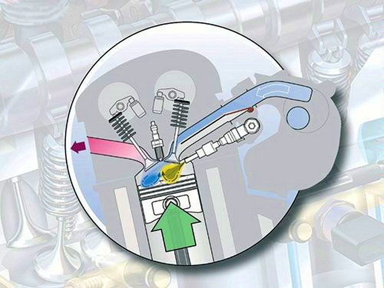
If the vehicle is exposed to full loading, such as high speed, heavy acceleration or fully loaded, the FSI engine enters homogenous mixture operation which increases compression, efficiency and performance. In this mode the 'charge flap' opens and air can flow into the combustion chamber through the full diameter of the manifold. This increased airflow is mixed with directly injected, cooled fuel to create a homogeneous fuel/air mixture throughout the entire combustion chamber. The direct injection of cooled fuel allows a higher compression ratio than what would be possible in a conventional naturally aspirated engine. This, in turn, produces a complete and highly effective combustion process that extracts more power from the same amount of fuel.
Golf TSI ‘Twin charger’
By Steve Carter
September 2005
The new Golf GT, to be launched at the end of 2005, will close the gap between the Golf Sportline and the Golf GTI. The GT will hit the market in Europe with two engine models - the innovative 1.4 1 Twin-charger and the equally powerful 2.0 TDI with diesel particulate filter as standard. Both engines produce 125 kW.
The Golf GT is not just very special under the bonnet; it also looks special. The new front section with its V-shaped radiator grille in the body colour is the exclusive preserve of the new Golf GT. Air inlet openings are integrated into the front bumper, but are more understated than in the GTI. In this way, the designers have clearly distinguished between the Golf, Golf GT, Golf GTI and R32, thereby making it clear that the models have different power levels. There is an opening for the twin tailpipe in the rear apron. The GT is 15 millimetres lower than standard, and sports 17-inch wheels.
As well as the 1.4 1 Twin-charger with 125 kW, Volkswagen is also launching the Golf GT with the most powerful diesel engine on the market and the most powerful that has ever been available ex-works in a Golf: the 2.0 TDI with 125 kW. The exceedingly frugal Golf GT 2.0 TDI is exciting to drive because it offers impressive power reserves in all situations. The direct-injection pump/nozzle turbo diesel with piezoelectric elements, four-valve technology, two overhead camshafts and a diesel particulate filter as standard develops 125 kW at 4000 rpm. Its torque curve reaches an imposing maximum of 350 Nm on a plateau from 1800 to 2500 rpm. The performance figures for this, the most powerful Golf TDI ever, are convincing across the board: It achieves a maximum speed of 220 km/h and accelerates from stationary to 100 km/h in only 8.2 seconds; and all this with a consumption of only 5.9 L/100 km of diesel.
As standard, the engine power is channelled to the driven front wheels through a manual six-speed gearbox. From early 2006, it will also be possible to combine these engine versions with the crisply shifting six-speed DSG direct shift gearbox. Connoisseurs will lick their lips at this, since the DSG combines the convenience of an automatic with the sporty and fuel-saving advantages of a manual. It has six forward gears, shifts gear extremely quickly and without any interruption in traction. The DSG is the ideal gearbox, particularly in combination with turbo diesel direct injection engines, and now also with the new Twin-charger. The DSG is the first gearbox to do full justice to the consumption benefits of the innovative engine technology in spite of the automatic gearshift function - indeed, it even adds to the benefits. Like the classic Tiptronic, this gearbox can also be shifted manually using a plus/minus gearshift gate.
The standard equipment of the Golf GT is based on the Trendline and includes electric front windows, electrically adjustable and heated outside mirrors, central locking with radio remote control, six airbags, headrests and three-point seat belts for all five seats, electromechanical power steering as well as ABS with electronic stability programme (ESP) and traction control (ASR).
The dynamically set-up Golf GT has a sports chassis lowered by 15 millimetres, 17-inch alloy wheels of the ‘BBS ClassiX’ design with 225/45 R17 tyres. The 40-cm brakes (as in the Golf GTI) combined with the brake assistant ensure that the Golf GT, both in the guise of the compressor-turbo and the most powerful TDI in the compact class, can be reined in safely.
At the Frankfurt International Motor Show, Volkswagen presented a ground-breaking innovation in the drive sector: The world's first twin-turbocharged FSI engine - the ‘Twin-charger.’ The compact 1.4 litre direct-injection engine develops 125 kW and has a maximum torque of 240 Nm, thanks to the combination of an exhaust turbocharger with a mechanically driven supercharger.

The 1.4 litre engine delivers a power output of 90 kW per litre, representing a peak value for a series production four-cylinder engine. Furthermore, the Twin-charger delivers a torque corresponding to a 2.3-litre naturally aspirated engine but with a fuel consumption around 20 percent lower.
Another performance variant of the innovative TSI engine, with 103 kW / 220 Nm) will be available from early 2006, initially in the Touran compact MPV, and after that the normal Golf and Jetta will also be available with this engine.
It is the declared objective of European carmakers to reduce CO2 emissions. This will be done in various steps, down to a value of 140 grams per kilometre. Reduction in CO2 emissions goes hand-in-hand with a reduction in fuel consumption. Achieving this ambitious target will require a combination of the latest engine technology with driveline optimisation.
However, this is not enough. As well as the consumption reduction, it was specified that there had to be a full torque characteristic combined with a high standard of quality and a long service life. In addition, the engine had to be compact to allow it to be integrated into many different vehicle concepts. And, it would have to be designed to enable straightforward production in high quantities. Another target was concerned with resolving numerous conflicting objectives in an innovative way. To cut a long story short – Volkswagen succeeded.
The most effective way to reduce consumption is downsizing. A reduction in cubic capacity means lower friction losses, resulting in a low specific consumption that equates to better efficiency. However, an engine with a low cubic capacity only meets the current requirements for active road safety and pleasurable driving to a very limited extent. As a result, the objective can only be achieved by boosting.
Classic small-capacity turbo engines boosted using exhaust turbochargers have only been used to a very limited extend in the past, since they only work at high rpms and have low moving-off power and are therefore less acceptable. This can be solved by using a mechanically driven supercharger, which supplies additional boost to the engine even at low speeds. The challenge was to combine these two systems in a rational way.
The only candidate for injection technology was the FSI (Fuel Stratified direct Injection) technology that is now used by Volkswagen in numerous model ranges. Experience gathered during the last few years by engine developers at Volkswagen had revealed that FSI could be ideally complemented by the two different supercharging techniques, the result being a previously unheard of increase in efficiency.
This gave rise to the world's first direct-injection engine with twin supercharging for use in high-volume series production - the ‘Twin-charger.’
The choice for the basic power unit was the EA 111 FSI engine series as used in the Golf in power levels of 66 kW (1.4-litre) and 85 kW (1.6-litre). The 1.4-litre engine is a four-valve four-cylinder engine with a swept volume of 1390cc and a bore/stroke of 76.5 by 75.6 millimetres. The focus in developing the ‘Twin-charger’ engine was placed on designing a new, highly resilient grey cast iron cylinder crankcase that could withstand the high pressure of up to 21.7 bar (2,200 kPa) over long periods. The engine also has a water pump with integrated magnetic clutch and supercharging technology.
However, the injection technology was also modified. A multiple-hole high-pressure injection valve with six fuel outlet elements is used. The injector, like that in the naturally aspirated FSI engines, is arranged on the intake side between the intake port and cylinder head seal level. The quantity of fuel to be injected between idling speed and the 90 kW/litre output power requires a wide variability in the fuel flow through the injectors. The maximum injection pressure was increased to 150 bar (15,200 kPa) in order to achieve a wide range of through flow. Furthermore, only FSI technology made it possible to include a compression ratio of 10:1, which is very high for supercharged engines.
The Volkswagen engine developers selected a compressor with a mechanical belt drive in order to increase the torque at low engine speeds. This is a supercharger unit based on the Roots principle. One special feature of the compressor used is its internal step-down ratio on the input end of the synchronisation gear pair.
The exhaust turbocharger also kicks in at higher engine speeds (with wastegate control). The compressor and exhaust turbocharger are connected in series in this case. The compressor is operated by a magnetic clutch integrated in a module inside the water pump. A control flap ensures that the fresh air required for the operating point can get through to the exhaust turbocharger or the compressor. The control flap is open when the exhaust turbocharger is operating alone. In this case, the air follows the normal path as in conventional turbo engines, via the front charge-air cooler and the throttle valve into the induction manifold.
One of the major challenges facing the development was to achieve the best possible interplay between the two superchargers arranged in series. Only when both units - the compressor and the exhaust turbocharger -complement one another optimally can the small power unit achieve its required level torque characteristic over a broad engine speed range, together with previously unheard of increases in efficiency.
The ambitious objective of squeezing in excess of 90 kW per litre swept volume could not be achieved with single-stage supercharging alone. However, an upstream compressor enables the boost pressure build-up of the exhaust turbocharger to be significantly increased.
The maximum boost pressure of the Twin-charger is approx. 2.5 bar at 1500 rpm, with the exhaust turbocharger and the mechanical supercharger being operated with about the same pressure ratio (approx. 1.53). A straight exhaust turbocharged engine without compressor assistance would only achieve a pressure ratio of about 1.3 bar here. The more rapid response of the exhaust turbocharger enables the compressor to be depressurised earlier by continuous opening of the bypass valve. This means compressor operation is restricted to a narrow map area with predominantly low-pressure ratios and, therefore, low power consumption. Consequently, the disadvantage of the mechanical supercharger system in terms of consumption can be limited.
In practice, this means the compressor is only required for generating the required boost pressure in the engine speed range up to 2400 rpm. The exhaust turbocharger is designed for optimum efficiency in the upper power range and provides adequate boost pressure even in the medium speed range. In dynamic driving, this is inadequate for in-gear acceleration in the low engine speed range. In these driving situations, the compressor is engaged to permit a spontaneous boost pressure build-up. The way in which these two systems complement each other means there is absolutely no turbo lag. The compressor is no longer needed above 3500 rpm at most, as the exhaust turbocharger can provide the necessary boost pressure even dynamically during the transition from coasting to full-load operation.
The compressor, with its high ratio of 1:5 in relation to the crankshaft, delivers a boost pressure of 1.8 bar even just above idling speed. This provides the power needed when moving off. An electromagnetic clutch integrated in the module of the coolant pump switches the compressor on and off. It is driven by an additional belt. A torque of 200 Nm is available at only 1250 rpm, and all the way through to 6000 rpm. In dynamic compressor mode, the automatic boost pressure control decides whether the compressor will be switched on in accordance with the tractive power required, or if the turbocharger alone can generate the necessary boost pressure. The compressor is switched on again if the speed drops to the lower range and then power is demanded again. The turbocharger alone delivers adequate boost pressure above 3500 rpm.
In practice, the 1400cc Twin-charger drives like a big naturally aspirated engine of about 2.3-litre cubic capacity. This is because the maximum torque of 240 Nm is available as low as 1750 rpm, and up to 4500 rpm. The boost pressure gauge installed as standard in the cockpit of the Golf GT 1.4 TSI is the only signal of the furious activity being undertaken by the superchargers, and the complex procedure of harmonizing both systems taking place under the bonnet. The driver likes it, because when the needle is fully deflected then the acceleration really presses the occupants back into their sports seats.
The smooth torque characteristic allows the driver to refrain from gear changes whilst still driving briskly. It goes without saying that the Twin-charger is much more free revving than a diesel engine. Indeed, the 1.4 TSI has a maximum speed of 7000 rpm. Thanks to this outstanding engine performance, overtaking manoeuvres on country roads are particularly enjoyable and much more rapid than is the case with a naturally aspirated engine. The value for in-gear acceleration from 80 to 120 km/h in fifth gear in 8.0 seconds can only serve as a reference here. Active safety has seldom been improved in this way without having an effect on consumption.
This is because very low consumption values are possible due to the generous torque and the high level of power that allow a correspondingly relaxed driving style. In the Golf GT, the 1.4 TSI gets along with only 7.2 L/100 km of Super Plus (98 RON) petrol. This is about 20 percent less than in a naturally aspirated engine with comparable torque and power (2.3 litres). In interurban transport the Twin-charger sips only 5.9 L/100 km.
In combination with the direct shift gearbox available for the ‘Twincharger’ from early 2006 onwards, the power developed by the 1.4 TSI will be appreciated even more due to gearshifts without any interruption in traction. And what is more, the advantage in terms of consumption, far from being reduced by this innovative automatic, is in fact increased.
It is possible to activate the winter programme using a switch in front of the selector lever in the centre console, to prevent too much torque being sent to the front wheels on a snowy or icy road. This reduces the moving-off torque and therefore prevents the drive wheels from spinning.
The second power variant of the TSI reveals that this innovative engine technology is not only intended for a sporty model variant but will also be used across the board. With 103 kW / 220 Nm, this engine variant will also appeal with its smooth and masterly engine performance. This variant of the TSI will be used first in early 2006 in the Touran.
The selection of materials that are resistant to high-temperatures does more than make it possible to keep consumption down to the best possible level at high speed. In spite of the high output per litre, the high-pressure level in the engine and possible engine speeds of up to 7000 rpm, the Twin-charger is designed for a long service life - with the same criteria that apply to all Volkswagen engines. More than 250 prototype and pilot series engines have been put through their paces in all necessary test cycles. Every single component of this new power plant has been designed for the engine service life and has come through its baptism of fire. Endurance runs corresponding to a mileage of 300,000 km have been successfully completed. The grey cast iron crankcase guarantees complete operating reliability even at the high peak pressures of up to 120 bar. The highly qualified personnel at the VW Chemnitz Engine Works use optimised production processes and the latest measuring technology to ensure that these high-tech power plants are assembled without defects.
The Golf GT TSI will be on sale for Australian buyers next year.