
Chassis & Suspension
Grafting a 1500 Bulkhead to a Superbug floorpan
Greasing the Kombi
Clutch Tube Repairs
Additional Chassis Bracing
Understanding Toe, Camber and Caster
VW Front End Rebuild
VW’s Electronic Stability Program (ESP)
Swing-axle VWs and Anti-Roll bars
Different types of VW 4WD
Grafting a 1500 bulkhead to a Superbug floorpan
By Lance Plahn
December 1996
Whilst working on your VW project, do you ever feel like a pioneer who is breaking new ground? I know I do sometimes, yet you know someone has done the job before. So you contact some people in the VW trade who advise they have heard about it but never seen or done it themselves. After reading volumes of material you can’t find anything relevant written on the subject.
This is a story of one of those adventures. However it is not a tech story on how to do it, but more a guide on how I approached it. The challenges that arose required a solution. A story like this requires lots of good detailed step by step photos to help make it successful.
My son and I are rebuilding a Kalita (similar to a Manx). It's mounted on a 1200 floor pan. You know, king and link pins with motion retarders (ideal for creek crossings), and a 1200 gearbox with swing axles. We wanted ball joints and discs up front and double-joint CV at the rear for better off-road traction. The obvious choice is a ‘76 pan, but they are very scarce, probably due to the small numbers sold in the one and only year it was available. The next choice was a 1500 auto pan, then weld in a clutch tube; however this required 90% of our project funds. So a very cheap Superbug was acquired, giving us a 1600 twin-port and double-joint rear end, complete with gearbox and suspension. All I had to do was weld on a 1500 front, which I had acquired some time ago. A friend had to put another pan under his 1500 because the frame horn cracked nearly all the way around on the driver's side under the axle. I have seen the six volt Type 3s do the same.
The first thing was to remove the bulkhead from the 1500 floor pan. This was done with the aid of an electric drill to drill out the spot welds, and an angle grinder to cut the welded sections. Set aside a few hours. The spot welds were across the top of the floor pan, forward of the body mounting cross over. The next row is under the pan, rear of the body cross over, or more precise, the raised section. I cut the body mounting crossover off and cut the tunnel in half in the middle of this cross over, giving plenty of tunnel to play with later on.
Next was to remove the Superbug front section from its pan. This took much longer, as the Superbug is considerably different in construction. But nevertheless, same principles. This time the tunnel was cut a few millimetres forward of where the body mounting cross over is welded to the tunnel. At this point the tunnel dips down then.
Now the challenges arise, welding the 1500 bulkhead to the Superbug pan. Firstly the distance between the body mounting bolts is further apart on the Superbug than the 1500. Also the 1500 bulkhead is narrower than the Superbug section. No problems, remove the whole anti-crush spacers from the Superbug pan, and move them into line up with the holes in the 1500 pan. Then when the 1500 bulkhead is welded in place, trim up the Superbug pan to suit, drill new holes and fill the old ones. The 1500 tunnel fits into the Superbug tunnel, enabling welding of the two tunnels in an overlap situation as opposed to a butt weld. The Superbug body mounting cross over is approximately 15 millimetres wider than the earlier models.
The next challenge is the 1500 pan is flat under the tunnel and bulkhead, whereas the Superbug drops just before the bulkhead and continues to the front. So when the 1500 bulkhead is mated to the Superbug pan, there is a section protruding down, like a scoop. So this corresponding section was cut from the removed Superbug front and grafted onto the 1500 bulk head and continuing back, mating with the dropped section, thus giving extra support under the rejoined section.
The fuel hose refitted without difficulty, which is a bonus. For best results, weld in the 1500 bulkhead with a mig welder. Of course much attention is directed to ensuring the whole thing is welded in square, continuously measuring the diagonals.
Greasing the Kombi
By Lance Plahn
October 1998
This time, we've got something for Kombi owners who like to get their own hands dirty. We all know Kombis are incredibly practical vehicles that offer huge payloads with plenty of economy. And if that's the case, doesn't it make sense to make them go as far as possible on as little as possible?
Working on that theory, one of the areas you can improve and squeeze plenty more miles from is the front end. Increasing the life of front ball joints is as simple as fitting a grease nipple, but you need to have a plan. And believe it or not, regular greasing of a half-worn ball joints will make it last as long as a brand new replacement unit. Not bad, right?
Fitting grease nipples to ball joints doesn't take long, but you will need to fashion yourself a special service tool for part of the job.
Start with the top ball joint - all you need to do is drill a 7/32-inch hole into the joint and fit a 6mm self-tapping nipple. It really is as easy as that. The bottom ball joint is a bit trickier because it's hard to get the drill to it. The best advice is to weld a 15cm length of 1/4-inch rod to the end of the drill bit so you've got a super long bit. No, it won't be straight, but if you take things slowly (a variable speed drill is best) you'll find the job can be done and you won't harm the bit.
Don't worry about metal shavings falling into the hole - all you need do is blow them out before screwing in the nipple. An even better idea is to add some grease to the drill bit so the shavings will stick to that and not fall in.
Once you've done that, you've got a completely serviceable ball joint that will outlast just about any other type. There are of course, some things to keep in mind. The most important of these is not to over-grease the ball joint. Over-greasing will result in the rubber boot bursting and that defeats the whole purpose because a broken boot will allow dirt and mud into the joint and wear it out very quickly.
Our suggestion is a thimble-full of grease every six months or so, depending on the mileage the vehicle does.
Now, on some Volkswagens, this particular modification will be even easier because some VW's already have a hole tapped into the ball joints. The cars we're talking about here are 1500 Beetles, 1968-69 Kombis and 1968-69 Type 3s. These will have a small plastic bung in the ball joint and all you need to do is remove this and screw your 6mm nipple in.
Of course, if they're not the original ball joints, it won't be so easy because later model and replacement joints don't have the threaded hole. In that case, just go back to the start of this page and follow the sequence.
Clutch Tube Repairs
By Lance Plahn
February 1999
All VWs have their problems, and more often than not there is a cheap and effective way around them, offering a better alternative than expensive repair-shop jobs. This tip on repair Kombi clutch tubes is a case in point.
The Kombi's clutch tube runs from just behind the front wheels to the front of the rear wheels, where it is spot-welded to the torsion tube. The clutch tube extends approximately 100 mm beyond this. A flexible guide tube, running to the retaining bracket on the gearbox, attaches this point. This tube should sag between 25 and 45 mm. Adjustments are made using 1600cc case washers - part number 043101129 - which are placed on the guide tube at the gearbox end. Same for Beetle.
The bracket on the torsion tube often breaks off at the weld, or the clutch tube itself may break at the same point, causing excessive freeplay that prevents the clutch from releasing properly. That's when you get the grating sound while you attempt to select gears.
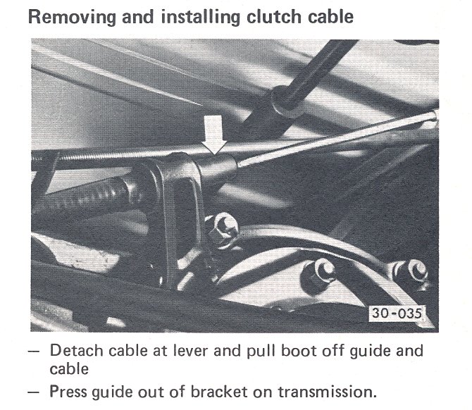
To repair, you'll need to remove the clutch cable and flexible guide tube, then return the clutch tube to its correct position; that is, it must be at the correct distance from the torsion tube and paced in line from the flexible tube running to the gearbox bracket. The clutch tube should tend to point down and should not be parallel to the ground. Usually everything can be aligned satisfactorily by using the old marks where the weld broke away.
When everything's aligned, place a new bracket up against the torsion tube and arc-weld into place. The bracket should run the same direction as the clutch tube; it is welded to the torsion tub and clutch tube. Note that the bracket should be located to leave enough clutch tube at the end so that the guide tube can slide on. Slide the clutch cable through, fit the guide tube, adjust sag and re-adjust clutch.
The job takes about a half an hour using a hoist, but a little more otherwise. There are many other way of doing this job, but we've found this is neat and strong and gives no more trouble. Often we repair customers' cars before it's needed to save the expense of a breakdown. We usually fit a grease nipple to the clutch tube, and remove, strip, clean and grease the front clutch pedal pivot at the same time.
Additional chassis bracing
By Steve Carter
May 1999
As any performance Beetle owner knows, if you keep launching your car hard and induce axle tramp you will eventually break or bend something; usually the chassis forks.
After speaking to a number of experts in this area and getting some conflicting information I decided to go with experienced drag racer Henry Spicak’s proven remedy.
This involved bracing the chassis forks to the rear luggage area. I accomplished this task by first getting hold of some banana type mountings from a Beetle towbar; you know the ones that clamp on to the chassis forks just near where the heater cables join the heater box levers.
I bolted these to my chassis forks, and then welded a piece of 25 mm square tube between the two, parallel to rear transmission mount cradle. I then welded another two pieces from the ends of the first square tube, then these went up to the underside of the luggage area terminating with a 6 mm thick plate that bolted to the floor of the luggage area. This plate needs to be about 80 x 80 mm, and you might as well make four of them because you will need another two on the other side of luggage area floor. I used some 12 mm thick Teflon sheet to go between the 6 mm plates and luggage area floor, to cut down on vibration from the chassis forks. The upright tubes need to go out at an angle of about 10-15 degrees so that, they end up about 50 mm from the wheel arches.
Now on the inside of the car you need another length of 25 mm square tube. I used thinner wall tubing for this one to cut down on weight. Cut this tube so that it just fits between the wheel arches, and allow room for this tube to be terminated with a 25 x 80 x 6 mm plate on each end. Make 8 of these plates.
Mount all the underneath tube and drill through the luggage area floor, then mount your second set of 80 x 80 mm plates and bolt them to the luggage area floor. Weld the inside piece of tubing to the 80 x 80 mm plates. It’s important to have the bolt holes on the 80 x 80 mm plate running north-south. Then drill the inner guard and mount another set of 25 x 80 x 6 mm plates on the outside of the inner guards.
By now you will come to the conclusion that the luggage area floor, inner guards and the chassis forks are all tied together, but there is one more step. Weld another piece of tubing to form a Y end section, starting above the area where the tubing is bolted to the floor. This then runs higher up on inner guard, terminating with another 25 x 80 x 6 mm plate, with another plate on the outside of the inner guard.
It’s best to only tack the unit together in the car, then take it all out again and give it a really good going over with the welder, and a coat of paint.
The other remedies that were recommended to me involved bolting a large piece of aluminium to luggage area floor and just bracing the forks to this. But that would be expensive, and it would only place stress on the luggage area floor instead of spreading the stress over the inner guards and luggage area.
Understanding Toe, Camber and Caster
By Larry Carley
January 2000
Every story has an angle, and this one is no exception. In this case, we are going to look at the three fundamental angles of wheel alignment: toe, camber and caster. For a better handle on where we're going, we need to start with the most basic of basics: what is alignment? Alignment is the geometrical relationship of the wheels to the vehicle itself, to each other and to the road. Ideally, each of a vehicle's wheels should be aimed straight ahead, be parallel to each other, be perpendicular to the road and be perpendicular to their respective axles. This will produce the least amount of rolling resistance, the least level of friction, the least amount of overall tyre wear and the most traction. But it’s not like that in real life.
Key Angle 1 is Toe. Toe is the most important wheel alignment angle because it has the greatest effect on tyre wear. Toe refers to the parallelism between the wheels as viewed from above, and is measured in millimetres. When both front wheels are aimed exactly straight ahead, with the distance between the leading edges of the front tyres exactly the same as the distance between the tyre's trailing edges, the wheels have ‘zero toe’ and are theoretically aligned. We say "theoretically" because toe alignment changes as the vehicle is driven. The joints and sockets in the suspension and steering linkage all have a little play, which, when added together, can allow wheel alignment to change depending on how the steering and suspension are loaded.
Likewise, the rubber bushings in the control arms have to deflect somewhat when the vehicle accelerates, turns, brakes or just cruises. This can also allow toe alignment to change. For this reason, toe is adjustable on all vehicles. Toe is adjusted by changing the length of the tie rods (equally on both sides, as a rule). Adjusting toe not only corrects any misalignment but also compensates for non-conformity in the steering linkage and suspension - which varies depending on the design of the vehicle, such as if it is front-or rear-wheel drive. That's why different toe settings are usually specified for different makes and model years of vehicles. The OE specifications typically call for a certain amount of ‘toe-in’ or ‘toe-out’, depending on the design of the vehicle and its steering and suspension systems.
Toe-in means the front edges of the tyres are closer together than the rear edges. Most rear-wheel drive cars and trucks have alignment specifications that call for a little bit of toe-in, say 1.5mm or so. This will produce zero rolling toe as the vehicle is being driven down the road because the natural tendency for the front and rear wheels is to toe-out due to rolling resistance and compliance in the steering and suspension. Toe-out is when the front edges of the tyres are farther apart than the rear edges. This may occur if the tie rod ends are worn, or if the control arm bushings have collapsed. Toe-out is a bad condition to have because it causes the tyres to scrub laterally as they roll along. As little as 3mm of toe-out will scrub tyres sideways 5 metres for every kilometre mile driven. At that rate, it doesn't take long to wear down the tread.
A classic symptom of toe misalignment is a feathered wear pattern across both front tyres. The direction of the feathering tells you if the tyres are toed-in or toed-out - rough edges towards the inside signal toe-in while rough edges to the outside indicate toe-out. But on radial tyres, toe misalignment tends to roll the shoulder of the tyre under as it scrubs, producing wear on the inner or outer ribs only. Toe-in will wear the outer rib while toe-out will cause wear on the tyre's inner rib. In both cases, wear can be aggravated even more if the tyres are under-inflated.
Replacing the tyres may replace the worn rubber, but it won't eliminate the tyre wear problem. New tyres will suffer the same fate unless the cause of the misalignment is identified and toe is reset to specifications. So anytime the tyres show toe wear, toe alignment should be checked to see if it is out of range.
Also, the steering system should be inspected for worn or bent parts. In addition to checking for loose or worn tie rod ends, look for bent steering arms or tie rods because either can cause toe wear, too. Strange as it may seem, on some front-wheel drive cars and minivans, a slight amount of toe-out (up to about 1.5 mm) may be specified when aligning the wheels to compensate for toe-in that occurs as the front wheels pull the vehicle down the road. Drive torque more than offsets compliance in the steering and suspension, allowing both front wheels to toe-in slightly when accelerating.
This is also what causes torque steer - a sudden steering pull - in some FWD cars that have unequal length half-shafts. Under hard acceleration, the left wheel with the shorter half-shaft experiences more toe-in than the right wheel with the longer half-shaft. This causes unequal toe changes and results in a steering pull to the right. Automakers have reduced or eliminated torque steer by using equal length half-shafts and/or stiffer control arm bushings. Worn or loose tie rod ends should always be replaced. But new tie rod ends won't necessarily cure a tyre wear problem unless the tie rods are properly adjusted after the new parts have been installed. Changing tie rod ends, tie rods or a steering rack will change the distance between the steering arms, which changes toe. So anytime parts are replaced, alignment needs to be checked and readjusted as needed. If toe is not within the vehicle manufacturer's specs (always use the specifications listed in an alignment reference manual or service manual), adjust as needed to bring toe within specifications.
The rear wheels on many vehicles have toe adjustments, too - typically those with independent rear suspensions (IRS), but also many front-wheel drive cars and minivans without IRS. Rear wheel toe misalignment can cause toe wear on both the front and rear tyres by creating a steering pull to one side. Unlike front toe, which is self-centring because of the steering linkage, a difference in rear toe angles side-to-side creates something called a ‘thrust angle’. The result is the same as rear axle misalignment that causes the vehicle to pull or lead to one side. Rear-wheel drive cars and trucks that do not have IRS have fixed rear toe settings and no adjustments. If the rear axle is square in the chassis, rear toe should be fine. But if the axle is bent or is cocked with respect to the chassis, it will cause rear toe misalignment.
One way to compensate for this kind of condition is to do a thrust angle alignment. This involves aligning front toe to the thrust angle created by the rear axle rather than the vehicle centre-line. On front-wheel drive vehicles and those with IRS, rear toe can be changed by using factory adjustments (where available) or by installing aftermarket alignment aids such as toe/camber shims, offset bushings, etc.
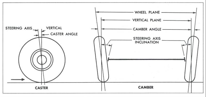
The next most important alignment angle is camber, which refers to the tilt of the wheels as viewed from the front or rear. Camber is the inward (negative) or outward (positive) tilt of the wheels. It is measured in degrees. As with toe, zero camber (perfectly perpendicular to the road) is the ideal alignment setting. But like toe, camber changes as the vehicle is being loaded or encounters a bump or dip in the road. The up-and-down motion of the suspension changes the geometry of the control arms and struts, which causes camber to change.
Many static camber alignment specifications may allow up to a degree of more of positive or negative camber depending on the design of the suspension. As a rule, camber settings should usually be within half a degree side-to-side. If camber is out of spec, a tyre will wear unevenly on one shoulder and the vehicle may pull toward the side with the most camber. Camber usually only affects one wheel, so if only one tyre shows unusual shoulder wear it is usually a symptom of camber misalignment. Keep in mind that camber applies to both front and rear wheels, though only vehicles with IRS typically have rear camber alignment specifications. Most rear-wheel drive cars and trucks with solid axles do not have rear camber specifications because there's actually no way to change it. Excessive camber can be caused by a bent spindle, misallocated strut tower, bent strut, worn or collapsed control arm bushing, bent control arm or a weak or broken spring. If any of these parts are replaced, camber should be checked and adjusted as needed after the parts have been installed. And for vehicles that do not have camber adjustments on the struts or control arms, or provide only a limited amount of adjustment, there are aftermarket camber adjustment aids that can help.
The third wheel alignment angle is caster, which is the forward (negative) or rearward (positive) tilt of the steering axis as viewed from the side. Caster is measured in degrees, and only applies to the front wheels because they are the only ones that steer (except for a handful of cars with four-wheel steering). Caster is a weird angle because it doesn't affect tyre wear directly, but it can indirectly because of its influence on camber. Caster's primary impact is on steering stability, steering effort and steering return. Most vehicles have a slight amount of positive caster to provide quick steering return and high-speed stability. This happens because caster forces the spindle to angle down slightly as the wheels turn. This lifts the chassis, bringing more weight to bear on the wheels as they turn. The net effect is that caster helps keep the wheels aimed straight ahead for improved steering stability, and helps the wheels return to the straight ahead position after turning. Many European luxury sedans have a lot of caster because it provides a more stable feel at highway speeds. The downside is that it increases steering effort and steering feedback to the driver.
What happens if caster is out of specification? If there is too much difference in caster side-to-side, it can cause a vehicle to drift or lead to one side. Some alignment specs call for a slight difference in caster to compensate for road crowns. But as a rule, caster should usually be within half a degree side-to-side. The tilt of the steering axis also causes camber to change when the wheels are steered. This is called ‘camber roll’. Excessive caster causes the tyres to lean when turning, which can result in accelerated shoulder wear. The same kind of problems that can cause camber misalignment can also cause caster misalignment: a bent spindle, misallocated strut tower, bent strut, worn or collapsed control arm bushing, bent control arm or a weak or broken spring. Again, if any of these parts are replaced, caster should be checked and readjusted as necessary after the parts have been installed.
Ride height can also affect caster. Spring sag or overloading a vehicle can alter ride height up to several inches, which can change caster readings by up to a degree or more. This may contribute to steering instability or change steering effort. That's why ride height should always be measured before checking wheel alignment. If ride height is below specifications, weak springs should be shimmed or replaced. Upgrade opportunities here include recommending variable rate replacement springs, air springs, overload shocks or air-assist shocks to customers who pull trailers or haul heavier than normal loads.
The only way to make sure your car’s wheels are properly aligned - and they achieve maximum tyre life - is to check wheel alignment periodically. Once set, wheel alignment shouldn't change unless parts become worn or damaged. Likewise, it makes no sense to attempt to realign the wheels until worn or damaged parts have been replaced. Worn parts will not hold an accurate alignment because they have too much play. There's also the danger that a component failure could result in the collapse of the suspension and/or loss of steering control (a broken ball joint or tie rod end, for example).
VW Front-End Rebuild
By Pat Ganahl
November 2000
You can't do it at home - but you can swap a rebuilt front suspension for the sloppy one in your VW.
Chassis lubrication - unlike changing the oil, cleaning the air filter, checking the points and plugs - is the periodic maintenance task most often neglected by most car owners. Out of sight out of mind, right? The squeaking hinge gets the oil, if it's lucky.
Chassis lubrication is critical for Volkswagens, especially early models. The owner's manual for pre- '68 Beetles specifies greasing the suspension every 3000 km (1500 miles). You could push it to twice that, but that still means every few months the way most of us drive. Later ball-joint models call for lubing every 10,000km (6,000 miles).
Ironically, a VW is one of the easiest cars to lube. Only the front suspension needs attention, and it only has four grease fittings per side. You can do it at home in a matter of minutes with a hand pump grease gun.
But most of us let it slide. If not, we have probably inherited a Bug that was neglected by at least one previous owner. Consequently, if you now own an early VW, especially a pre-'68 model, chances are the front suspension is worn out, for three reasons: 1. Because it wasn't greased regularly; 2. Because even a properly maintained suspension is bound to wear out after 30 years of use, and 3. Because rebuilding the VW front end properly requires several large jigs and presses not found in most repair shops.
So if you're driving a VW with sloppy suspension, which is likely, you won't be able to fix it at home. But there is good news. First, the entire front suspension and steering system of your Bug unbolts quickly and easily from the chassis as a unit. You can remove it in your driveway with simple hand tools. Secondly, since there are still a lot of Bugs on the road, a few large VW workshops will have tooled up to be able to rebuild VW front ends. All you have to do is pull out the old unit and swap in a rebuilt one, a job you can do in about half a day. You should be able to get a rebuilt unit for about $650, exchange.
First of all, how can you tell if your front end is worn out? Initial telltale signs are wandering or loose steering, uneven wearing of the front tyres, or a clunking sound as the car rides over bumps. To further check, jack up the front end, make sure both spindle nuts are tight (to snug up the wheel bearings), then shake each tyre both top to bottom and side to side. If there is any appreciable freeplay, the front end needs help.
Before you start unbolting anything, place an order with the rebuilder for a new unit one or two weeks ahead of time. They can make up a proper front end from parts on hand and have it ready to exchange when you bring your old one in. To do so, however, you must determine exactly which unit is in your car. In Australia, 1967 and earlier (ie. 6-volt) VWs have a ‘link and pin’ arrangement, where the spindle turns on a king pin. Later models use ball joints. Some 1968 ball joint units have a smaller inner spindle bearing (wheel bearing) and smaller tie rod ends than later models. The easiest way to tell them apart is to fit a spanner on one end of the tie rod retaining nuts. If it's 17mm it's the earlier type; if it's 19mm it's the later one. Also, 1960 and earlier VWs used a worm and sector type of steering box which cannot be rebuilt, unlike the recirculating ball type box used on later models. However, it can be replaced with a new universal type box that is available from VW shops for about $150.
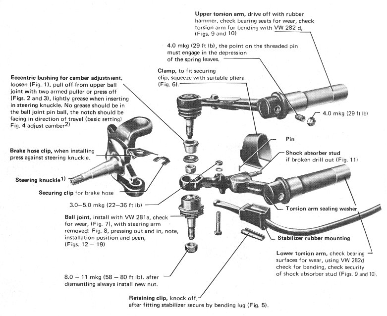
The rebuilding process involves at least a dozen operations, depending on the type of front end you're getting. The job starts with steam cleaning and disassembly. Loose parts are further cleaned in a jet degreaser. The bare beam is straightened both laterally and vertically on a pair of special jigs set in 10-tonne presses. Likewise, each of the four trailing arms is checked for alignment in a special jig, and straightened if necessary in a hydraulic fixture. Each spindle is chucked in a lathe and checked for straightness (to a maximum 0.15mm runout) with a dial indicator. Another large press and fixture is used to get them true. Finally, the tie rods are cold straightened by hand.
Each of the above steps is necessary, because the VW front end has a tendency to bend at several points if the car is involved in a collision or the tyre hits something like a kerb. Accurate alignment of the front end depends on the exact straightness of each component.
Disassembly and reassembly of ball joint and link pin varies, of course, with the earlier link pin spindles being the more complicated. Ball joints are simply pressed out of the trailing arms with a 10-tonne press. Link pin spindles require removal of link pins (which attach the steering knuckle to the trailing arms), pressing out link pin bushings, pressing out the king pin, and pressing out the king pin bushings. For reassembly, each of the new components must be accurately pressed back in, and the bushings must be honed exactly for proper king pin fit.
Before the front end is put back together, the parts are cleaned once again in a large Goff metal shot blaster and the beam is painted. Then the torsion bars are greased and reinstalled, the inner Babbitt bearings are checked (they're usually OK), and the outer needle bearings are replaced if worn. New grease seals are installed, and the trailing arms are slipped into the tubes.
Meanwhile, the steering box is being disassembled, cleaned, rebuilt, and then adjusted prior to attachment to the beam. Finally the spindles are reinstalled on the trailing arms either with new ball joints or link pins, the tie rods are reinstalled with new ends, and a new steering damper and shock absorbers are attached. As you can see, the rebuilding is thorough and complicated, yet not overly difficult for a VW workshop.
When the new front end is ready, it's time to take the old one out of your car. Jack up the front and place jack stands under the pan, behind the front axle. Remove the dust cap from each wheel, unbolt the spindle nuts, and remove the wheels and brake drums as a unit. Pull off the inner wheel bearing races and save them. Then remove the three bolts that attach each backing plate to the spindle and remove the backing plates and brakes as a unit. Don't disconnect the brake lines (so you won't have to refill and bleed the brakes later); just let the backing plates dangle behind the axle, out of the way.
Next, disconnect two bolts attaching the steering column to the steering coupler, and remove the longer tie rod from the pitman arm on the steering box.
Now all that holds the front end to the car is six bolts. The four at the front of the beam are easy to see and remove. Two more, directly above these, are accessible behind the spare tyre on '60 and earlier VWs. On later cars, loosen the fuel tank and raise it slightly to get a spanner on the top bolts. Once the bolts are out, it helps to have an extra body present to lift the unit to the ground. Remove the steering
coupler, and cart the worn-out unit off to trade it in for a new one.
Obviously, reinstallation of the new front end follows the above process in reverse. Before you start, it's a good idea to install a new steering coupler, since the old one is probably sloppy.
Once the new unit is in the car, you may have to loosen the steering box bolts and rotate the box slightly to line up with the steering shaft. Remember to centre the steering before bolting it back together, so the wheel will be right side up and the blinkers will cancel properly.
To complete the rebuild of the front end, you should also consider replacing the inner and outer wheel bearings and the brake linings, but obviously this depends on their condition. At any rate, be sure to repack the wheel bearings and adjust the brakes.
The final step is to align the front end. If you have a ball joint unit, take it to a VW workshop. If you have a pre-'68 VW however, all you need to do is set the toe in, and you can do this at home. Make a fixture that will hold a scribe of some sort (a long nail driven through a piece of wood will work). With the tyres jacked a few cm off the ground, place the scribe on the ground under the wheel and spin the tyre by hand so that you make a straight line in the middle of the tread around the circumference ol the tyre. Do this on both tyres. Then, with the help of a friend, use a long tape measure to find the difference between the scribed line at the front and at the back of the tyres. Loosen the lock nuts at both ends of a tie rod, and with a large pair of pliers, turn the tie rod one way or the other until the distance between the front of the tyres is 3mm less than the distance between the lines on the back side of the tyres. When it's right on, tighten the tie rod lock nuts.
Last, but surely not least, lubricate the new front end at all grease points. Pump the grease in until it starts to curl out of the points. And we shouldn't have to tell you - From now on, grease it regularly according to the VW schedule, so you won't have to repeat this job again for a long, long time.
VW Electronic Stability Program (ESP)
By Paul Grimes
April 2002
With the recent announcements from Volkswagen that Electronic Stability Program (ESP) will be standard on all of their European models, I felt it was a good time to provide some insight as to how this system functions and what its purpose is. The true advantage of this electronic device is its ability to identify and compensate for critical driving situations. ESP monitors the car's progress continuously and takes action automatically if there is any risk of the car going out of control.
The first application of the Bosch ESP system was in the Mercedes Benz S-Class in 1995. Mercedes is now offering ESP as standard equipment on all of its vehicles worldwide. Audi has been equipping all of its top-of-the-range automobiles in most European countries with the ESP package since the beginning of 1999. Interestingly this means that ESP has established itself in the automotive market faster than any other safety equipment, including the air bag.
The ESP system is a ‘marriage’ of the vehicle's ABS system with a newly designed electronic control unit (ECU) that features a new, second-generation 56 Kilobyte microprocessor. The newly-scaled processor takes in a variety of sensor data, switch signals, and valve commands to aid the vehicle in maintaining a consistent and predictable level of control while performing evasive and high speed cornering and braking manoeuvrers.
The yaw sensor, the ‘heart’ of the ESP, is produced with high precision silicon micro mechanics. The sensor's design was patented by Bosch in 1998, and is designed to consistently monitor the vehicle's tendency to rotate around its vertical axis. The newest generation of the yaw sensor is one third smaller than its predecessor due to the wide array of applications, and has become more cost effective as the development has continued to refine the product. The sensor has a weight of approximately 70 grams and a volume of 45 cubic centimetres. The system incorporates a primary pressure sensor to improve braking control under extreme pressure. Furthermore, the system carries a self-system test when the ignition is on, and does its own self-diagnosis.
In practice, the system detects movements that could indicate a ‘skid condition’ for the vehicle, which is detected by the shift of micro-fine comb structures of the spring-mass system, causing a change in the event of rotational movements of the vehicle on a vertical axis. The rate of rotation, along with the measure of transverse acceleration, is evaluated by the ECU. The car's yaw behaviour can vary in three ways:
1. The vehicle can respond to steering wheel movement and make a turn while remaining stable. Depending on road speed, each steering angle is equivalent to a specific yaw rate.
2. The car can begin to oversteer, and its tail run wide. It then rotates more rapidly round the vertical axis than if it were cornering in a stable manner, and the yaw rate is thus too high.
3. The car may understeer severely, in which case it is the front wheels that try to run wide. Steering wheel movements produce too little response, so that the yaw rate around the vertical axis is slower than it should be.
ESP has only a fraction of a second in which to correct such critical dynamic patterns. The aim is to maintain stable cornering in all circumstances, and ensure that the car responds in the correct way to the driver's steering-wheel movements. These movements are then processed to deliver the signals that are sent to stabilize the vehicle through the combination of ABS, TCS, and throttle position.
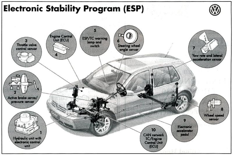
A simple process, though the ESP systems computer has a great deal of work to perform in a very short time. This is because ESP not only processes the yaw rate signals, but also those from a steering angle sensor mounted just behind the steering wheel, from a lateral acceleration sensor and from the four wheel speed sensors. From all these data it compares the steering angle and wheel speeds with the yaw and lateral acceleration rates, and detects any departure from the desired values. It then determines where and to what extent the wheel brakes should be applied.
ESP can modulate the braking forces at the individual wheels to correct vehicle motion patterns. As an example, if the vehicle rear end were to spin towards the left under a panic manoeuvre, the ESP system compensates by generating a pulse to the left front wheel to pull the car back into a straight line. ESP can also ‘dial in’ specific engine power delivery changes to correct the car's diversion from a straight line, either during deceleration or acceleration. ESP can also help to ensure that stopping distances in corners and on road surfaces that have differing traction levels from left to right side.
Although ESP monitors the car's movements continuously, its action will not be noticed by the driver unless the car should become unstable. Incidentally, the driver can switch off ESP by pressing a button. This provision is mainly to enable ASR, which is an element of the complete ESP system, to be put out of action in certain driving situations. ESP represents an important milestone in vehicular safety. It has won numerous awards for innovation, including some issued by the German Automobile Insurers Association and the Institute for Vehicle Safety in Munich.
Swing-axle VWs and Anti Roll bars
By Greg Mackie
May 2003
So you think the fitting of an ‘anti-roll bar’ to the rear of your swing axle Volkswagen will improve its handling? Well, think again.
The fitting of an anti-roll bar to the rear of any vehicle will shift the handling balance towards oversteer. Conversely the fitting of an anti-roll bar to the front of any vehicle will shift the handling balance towards understeer.
All cars will understeer as they enter a corner. As cornering forces increase, rear-engined VWs switch from understeer to oversteer and at their cornering limits they oversteer very strongly. So why would you want to fit a device that promotes oversteer? The factory never did.
Resistance to roll, generally is a good thing for a car's handling, is the enemy of swing axle suspension systems. When cornering a swing axle Volkswagen, it desirable for the outer loaded wheel to roll up into the body of the vehicle. Unfortunately the suspension system resists this happening. The road surface applies a sideways force to the tyre, which tries to rotate the swing axle under the vehicle. When the cornering forces are high enough this is exactly what happens (the dreaded ‘tuck under’).
So how do you improve the handling performance of swing axles? Simple, you must reduce the roll stiffness of the suspension system.
This can be achieved by
1. Fitting softer torsion bars. Not practicable as this will reduce the load capacity of the axle.
2. Widening the track. This can be done by fitting wider wheels, but the handling gains due to a wider track alone are small.
3. Lowering the rear axle by adjusting the torsion bars, which will also significantly widen the track. However excessive negative camber will starve the wheel bearings of oil, which are splash fed from the transmission. Lowering the rear axle also reduces the load capacity of the axle.
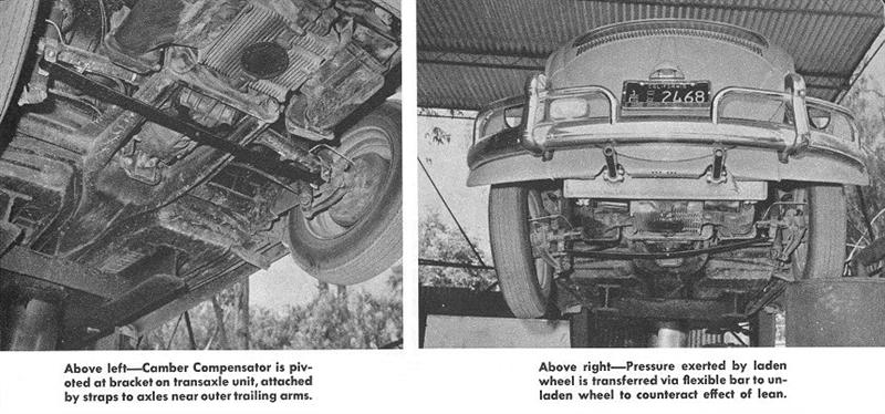
4. Fitting a camber compensator. Fitting a camber compensator without lowering the rear axle will not reduce roll stiffness; it will simply increase the load capacity of the axle. However if the axle is lowered and excessive negative camber is reduced by correctly fitting a camber compensator, you will have achieved reduced roll stiffness, a wider track, a lower centre of gravity and retained most of the load carrying of the axle. Wider wheels will enhance the set up.
Look at Porsche to see what they do. They fitted a camber compensator – a transverse leaf spring – to the swing-axle Porsche 356 to improve its handling. Joe Vittone, the founder of EMPI, sold both Porsches and Volkswagens at his LA dealership in the 1950s and he quickly realised that a Porsche-style camber compensator would help the VW. EMPI was one of the first companies to make and sell them.
So what is a camber compensator? Perhaps a few definitions will help.
First, what is an anti roll bar? It is a device that carries no axle loads (vehicle weight) but does increase the roll stiffness of the suspension. That is, it only works when going into a corner and one side moved. It ‘resists’ this happening and makes it stiff.
What is a camber compensator? It is a device in the form of a simple leaf spring that, when correctly fitted, carries some axle load but does NOT increase the roll stiffness of the suspension. On some formula vees the camber compensator carries the entire rear axle load! With this arrangement roll resistance is provided by the front axle only.
Ah, but what about the ‘Z bar’? This is a torsion bar device that fits across the top of the transmission. Like the camber compensator it shares vehicle loads with the principal suspension members, but offers no resistance to roll. It was NOT an ‘anti-roll bar’. The VW factory fitted Z bars to swing axle Beetles from the 1500 model onwards in Australia. These models also had a much wider track and softer torsion bars, all in the interests of reduced roll stiffness and better handling. As fitted by the factory, the Z bar only contributed to load sharing when the vehicle was loaded. Unloaded the Z bar had no effect.
Camber compensator bars and Z bars serve exactly the same purpose. Road and Track Magazine had a very good article, published in the sixties, on how to improve the handling of a swing axle beetle. Jack Bono ran a VW speed shop, in Sydney, in the sixties. He fitted camber compensators of his own design and understood the principles involved.
But what ever you do to a swing axle it will remain a cheap and nasty suspension system that will bite you severely whenever its limits are reached and tuck under occurs. (Unsafe at any speed Mr Nader? Well almost, but not quite.) If you do raise the handling limits of your swing axles, tuck under will happen at a higher speed, with much more severe consequences.
The Porsche 911-style double-jointed rear axle system fitted to semi-auto Beetles, all Superbugs and the Australian ’76 Beetle has none of the vices of swing axles and any serious performance race car project should be on a double-joint pan.
And if you have an anti- roll bar fitted to your swing axles, please think again.
Different types of VW 4WD
By Hans Bleeker
April 2004
Torsen differential - Audi Quattro system
Being the master of 4-wheel drive, Audi always insists on using the most effective system, regardless of price. Its ‘quattro’ 4WD system uses a purely mechanical Limited Slip ‘Torsen’ differential.
Torsen means ‘torque-sensing’, and was invented by an American company called Gleason Corporation. Its slip-limiting ability is implemented by cleverly using a worm gear/worm wheel pair. This pair has a special characteristic: driving torque can be transferred from worm wheel to worm gear, but not the reverse. Otherwise, they will be locked up. It is this characteristic that limits slip.
Here is how the Audi Torsen differential works. In normal cornering, with no typre slip in any wheel, the Torsen differential provides the same function as a normal differential. The addition of the worm wheel/worm gear pair does not affect the speed difference between output shafts. If the car turns left, the drive shaft to right wheel runs faster than the differential housing, while the drive shaft to left wheel runs slower than the differential housing. The speed difference between left and right worm wheels can be exactly matched in the synchromesh gears. Note that the worm gears / worm wheels pair do not lock up because torque is transferred from worm wheels to worm gears.
When one of the wheels, say the right wheel, loses traction due to poor road surface or whatever reason, the worm gear / worm wheel pair get into effect. At the instant just before they become effective, one must know that according to normal differential practice, no torque will be sent to the left wheel, which has traction. Instead, all the torque will be sent to the spinning right wheel, which would normally make it spin even more. But with the Torsen diff, the fast-rotating right worm wheel will drive its worm gear, through the synchromesh and drive the left worm gear. Now, do you still remember the basic characteristic of worm gear / wheel pair? Well, when worm gear drives worm wheel, they will be locked up. As a result, the left worm gear and right worm gear are actually locked together, thus wheels on both side will rotate at the same speed and get the car out of the loss of traction.
Except the first generation quattro system that appeared in the early coupe (it used a 4WD system from the VW Iltis!), most of the subsequent quattro systems have used Torsen differential in centre and rear axles. This is rather expensive! However, Torsen-equipped 4WD has many advantages. First of all, its pure mechanical parts react almost instantly to tyre slip. Secondly, it provides linear lock-up characteristics. Thirdly, it is a strictly permanent 4WD system. In normal condition, torque split between front and rear wheels is 50:50 (other ratios are possible, depending on the pitch of worm gears).
Apart from Audi, few other carmakers have adopted Torsen LSD, mainly because of cost reasons. Toyota's rally car, the Celica GT4, was one of the few exceptions. It used Torsen in the rear axle. This might be part of the reason why it was so expensive compared with competitors, and Toyota no longer competes in the WRC.
Advantage: Quick response, permanent 4WD
Disadvantage: Pricey, torque split not variable
Who uses it? All non-Golf-based Audi quattro models, Toyota Celica GT4, Hummer.
Note that the name ‘quattro’ traditionally refers to the traditional Torsen system used in almost all modern Audi quattros until the arrival of Audi TT (which uses the Haldex system). Since then the name ‘quattro’ has become an Audi marketing trademark, rather than indicating the actual mechanism. At the time of writing, all Audi Quattro models, excluding the Golf-based A3, S3 and TT, still employs the traditional Audi Torsen system.
Viscous-Coupling differential
Viscous Coupling centre LSD is commonly used in many simple 4WD systems. One of the earliest examples was Volkswagen's Syncro system, used most famously on the T3 Transporter but also on the Golf and Passat Syncros. VW’s systems were designed and built by specialists Steyr-Daimler-Puch in Austria.
Inside a viscous coupling there are many circular plates positioned very close to each other. Both drive shafts connect to roughly half of the plates in an alternating sequence. The sealed differential housing is full of a high viscosity silicone-based liquid, which has a strong tendency to ‘visco’ those plates together.
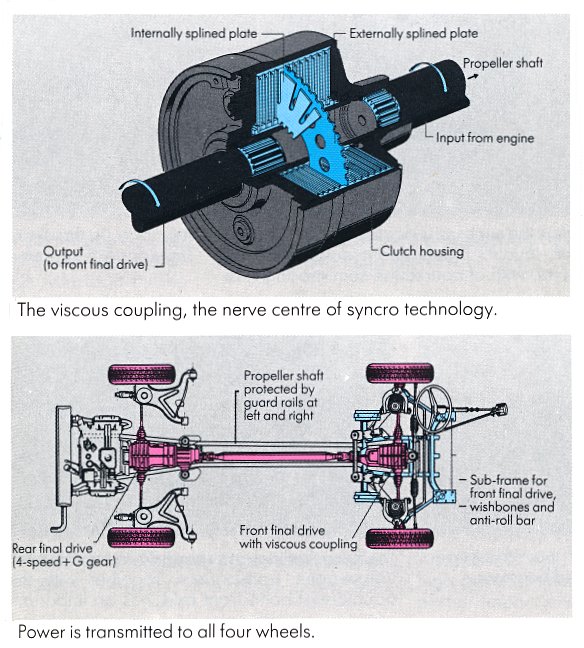
In normal conditions, the front and rear axles run at roughly the same speed so the plates and viscous liquid are relatively stable to each other. When tyre slip occurs in one of the axles, then alternating plates will be running at different speeds. The properties of the special viscous liquid will then ‘lock’ and try to ‘visco’ them together. As a result, torque is transferred from the faster driveshaft through the liquid to the slower driveshaft. The greater the speed difference, the larger the torque transfer. As a result, limited slip function is implemented.
Note that Viscous-Coupling LSD is a speed-sensing device. Under no-slip conditions, no torque will be sent to the other axle. Whenever slip occurs, theoretically up to 100% torque can be sent to any axle, depending on the traction difference between front and rear axle. Therefore it is a part-time 4WD.
Being a part-time 4WD, it does not have the neutral steering of a permanent 4WD can obtain. For cars based on rear-wheel drive models, such as Porsche 911 Carrera 4, this is not a real problem - as normally the car runs like a RWD car, and thus is capable of delivering the desirable throttle oversteer. However, for other front-wheel drive-based cars like VW Golf Syncro and Volvo 850 AWD, the part-time 4WD can do nothing to correct their understeering manner. This is the first disadvantage.
The next problem is the delay before the 4WD takes effect. Since viscous liquid is not a fixed medium (unlike a gear), it takes time and speed difference to be effective. The function between speed difference and torque transfer is an exponential function - that means in the early stage of slip, torque transfer remains near zero.
To cure this problem, most manufacturers vary the final drive ratio such that a slight speed difference is incorporated, even in normal conditions. As a result, the vicous diff is ‘slightly’ locked all the time and the car actually runs with say a 95:5 torque split between front and rear. This shortens the delay time. However, it is still impossible to match the pure mechanical Torsen LSD in performance.
It might be less effective than Torsen system, but it is certainly the cheapest, so we can find it in many mass production 4WD cars.
Advantage: Cheap and compact
Disadvantage: Part-time 4WD only. Normally feels like 2WD.
Who uses it? VW Syncro, Lamborghini Diablo VT, Porsche 993/996 Carrera 4 and Turbo, Volvo 850 AWD etc.
Volkswagen-Haldex system
Since late 1998, Volkswagen has replaced the older viscous-coupling Syncro system with a new 4WD system called 4Motion. First shown in Audi TT and Golf 4Motion, the new system uses a multi-plate clutch centre differential developed by a Swedish company, Haldex, and computer software from Steyr-Daimler-Puch.
At this moment it is only offered for the transverse-engined platforms such as the Golf/Jetta, and Transporter, but there is no technical reason that prevents it from being used on Audi's longitudinal-engined models as well.
The Haldex centre differential is similar to Porsche 959's PSK system, except for being smaller, simpler and cheaper, thus making mass production feasible. The centre differential is mounted near the rear axle and just in front of the rear differential.
Its clutch consists of 6 discs, immersed in oil bath to reduce friction. Actuation is made by hydraulic pressure. Normally the input and output shafts rotate with a speed difference (which could be implemented by different final drive ratio), so therefore the discs are rotating relative to each other. When no pressure is applied, the clutch is not engaged thus torque will not be transferred to the rear axle. Increase the pressure on the multi-plate clutch, and the latter will be partially engaged, thus sending torque to the rear axle. The more the clutch engages, the more torque transfers to the rear axle.
The computer determines how much torque to be sent to the rear wheels. Normally it is 50:50, but in tight corners when wheels on one of the axles are slipping, the driver can easily feel the torque is transferring from one to the other axle. Volkswagen claims 100% torque could be sent to either axle.
Compared with the Porsche 959's unit, Haldex's unit has 7 fewer discs in the clutch. This makes the Haldex unit more compact and cheaper. The down side is it is not capable of handling as much torque (the 959 had 500 Nm; the Audi TT has 280 Nm). In addition, the 959's discs were organised as 6 pairs of independent clutches, each actuated by individual hydraulic actuator. The Haldex has just one actuator, acting on all six discs; again, this saves weight and cost. However, this cannot vary the amount of torque split as precisely as the 959’s independent (but very expensive) clutches.
Based on journalists’ comments about the handling of Audi TT and Golf 4Motion, it seems that the 4Motion system performs even better than the traditional Torsen differential quattro, in their opinions. Perhaps the age of the Torsen quattro is passing away.
Advantage: Inexpensive and quite compact
Disadvantage: Unknown torque-handling ability.
Who uses it? Audi TT, Golf 4motion and all 4WD versions of Golf derivatives.
Note: ‘4Motion’ does not always imply a Haldex 6-disk system. Volkswagen also use the term ‘4Motion’ to describe the Torsen-LSD system used by the Passat. Therefore, like ‘quattro’, ‘4Motion’ is actually a marketing nameplate instead of indicating the mechanical design.
Volkswagen Touareg & Porsche Cayenne EDL 4wd system
This all-wheel-drive system is all-new, as both companies wanted a vehicle that is as capable off-road as it is on the road. The fully electronic AWD system utilizes electronically controlled differentials that can be programmed to respond to both pre-mapped preferences (say a 30/70 front to rear wheel drive bias) and to varying conditions of both slip and driver demands. For instance if full throttle is applied from a stop, the system will use actual throttle measurement to apply more torque to the rear wheels in anticipation of front slip; as opposed to a system that must detect slip first before diverting power or locking differentials. The system will still detect slip though, and divert more power to the wheels that need it most.
The system employs an inter-axle differential lock, and also has a true low-range gear set for those demanding conditions that warrant it. Towing capacity is 3500 kg, and Volkswagen claims more than 28 cm of ground clearance and the ability to ford through water up to 60 cm deep.
The AWD system in the Porsche version will reportedly be set with more rear power bias than the Volkswagen, in order to give it more traditional Porsche handling and power characteristics. However, the Volkswagen application will reportedly be more suited to hard-core off-road usage due to different programming of the AWD system electronics and its more neutral handling characteristics.
Both models will be highly capable off-roaders according to engineers from VW and Porsche as they benchmarked the Touareg and Cayenne against all major competitors available including Jeep, Mercedes, BMW, GMC and others.