
Exhausts
Käfer – Auspuff 1
Käfer – Auspuff 2
Käfer – Auspuff 3
Käfer – Auspuff 4
Exhaustive Research
Exhaust Gas Analysers
Exhaust Basics
Exhaust Wrapping
Fix your VW Heater
Käfer – Auspuff 1
By Rod Young
December 1986
This quite descriptive-sounding German heading means ‘Beetle Exhaust’. This will be the first of a series of articles showing what has been done and what you can do to improve the standard VW exhaust system, and a bit of theory.
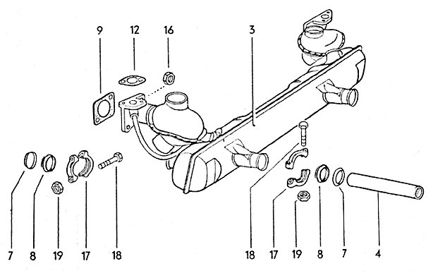
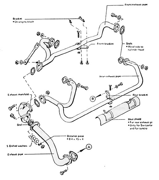
First, a description of the stock late Beetle system, which should not be condemned out-of-hand as it is a very well-designed piece of equipment, all things considered. Exhaust gases flow from the front cylinders, 1 and 3, through a heat exchanger on each side. From there they enter the main box chamber, but have to pass through two small perforated cones first. The exhaust gases from the rear cylinders, 2 and 4, go straight into the box chamber, the exhaust ports being very near at this side. From here they go through two pipe extensions to the other side of the chamber, then through some baffles. This is how the factory has ensured that each cylinder blows down an equal-length of pipe. Once the gases are in the large chamber, they can only flow through the tailpipes. These are an outer tube, inside of which is a perforated inner tube, and fibrous material sandwiched in between.
The standard Volkswagen exhaust fulfils very effectively the following criteria:
- Low noise output (this is entirely relative
- A pleasant-sounding ‘beat’, achieved through equal-length tubing
- Good ground clearance
- Low weight
- Provision for a heater
- A non-obtrusive appearance
- Reliability
Two more design criteria, which are more important for the factory, are:
- Ease of manufacture at little cost, and
- A throttling of engine output
This last criterion is intentional, as the Volkswagen engine was never supposed to be efficient in its power output. If this last aspect is to be improved upon, and that has been the main aim of many of us, it is likely that many of the other criteria will have to be compromised.
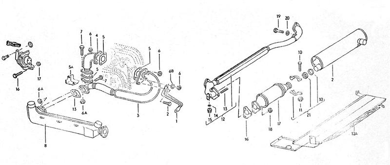
Above is the exhaust system used on Beetles destined for the U.S. and Japan, from about 1975 on (not in Australia). It’s a pretty expensive-looking set of pipes, and on the catalytic converter models, power was definitely down over the normal exhaust. Only one tailpipe was used.
Next issue – how to improve the stock system for more power.
Käfer – Auspuff 2
By Rod Young
February 1987
This month’s article deals with how to modify the standard VW Beetle exhaust for more power.
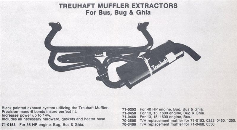
This advice can only be given thanks to a bit of fortuitous experimentation. A few years ago, after returning from a trip overseas, I went to start my Beetle, which had been sitting dormant for over a year. It had been fitted with a set of tube extractors, but these had rusted out with the enforced wait, and as soon as I started to drive the VW up the street, big holes were blown out the exhaust system! I couldn’t afford to buy another similar system, but I was able to scrape up enough cash to buy a stock muffler. I was reluctant to do so, as the engine was extensively modified, and I thought it would be a waste to strangle it with a restrictive set of pea-shooters. So I thought I’d see about making the stock system a little more free-flowing.
I had previously seen a cut-away VW exhaust, and I knew the layout of the pipes inside. The bottom pipes from cylinders 1 and 3 end in cone-shaped baffles where they hit the muffler box, and the top pipes from cylinders 2 and 4 enter the muffler and cross over to gain extra length and are capped at the ends. It was at the end of these entry pipes that work would need to be done, as the cross-sectional area is severely restricted at these four points.
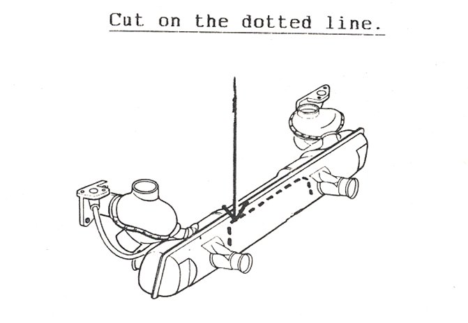
I was expectant and none too cautious in setting about chiselling open the skin at the back of the muffler and peeling it back. This non-genuine ‘Leistritz’ brand muffler was a little bit different from the genuine VW article that I had seen before, in that the top pipes did not cross over but ended in perforated sheet-metal baffles. It was clearly inferior to the genuine VW, as the pipes were not tuned-length. However, the points where I could cut away some material were now obvious.
The cone-shaped baffles were completely cut away with an oxy-acetylene torch and the perforated sections cut out of the baffles in the middle of the chamber, so that no obvious restriction remained. The skin was then rolled back into place and welded up. For good measure, I thought I’d replace the tailpipes with something bigger. The stock tailpipes communicate to the same chamber and thus offer a parallel flow path for exhaust gases. Even so, the effective cross-sectional area is quite small. I welded in some lengths of 35mm stainless-steel tube in place of the tailpipes, and thought I had then finished.
When I started up the motor again after assembly, the noise level was so high that I thought, “My God, what have I done?” Since I had to drive the car, I rammed the stock tailpipes up inside the stainless steel tubes and secured them with self-tappers. Much to my surprise, the car once again sounded exactly like a stock Beetle, and didn’t go too badly! It was obvious that the tailpipes did all the work of suppressing noise, and that baffles inside the muffler box serve only to restrict the flow of gases (don’t forget that VW engines were designed as a low-output, throttled powerplant), and perhaps to smooth out the pulsations a bit.
I still wanted to optimise the system for power, and didn’t mind a slightly more sporty sound, so I fabricated some new tailpipe inserts out of 32mm stainless tube, drilled about 50 small holes in each of them and wrapped them in asbestos string, then pushed them up into my larger tailpipes and secured them.
Now I had the best of both worlds. I didn’t notice any drop-off of power from the extractor system, though it had been over a year…it definitely went better than a stock system though, and I left the thing on the car until it rusted through. A friend who was following me going up a hill at full power one night noticed neat blue flames curling out of each tube, so the mods must have made some difference.
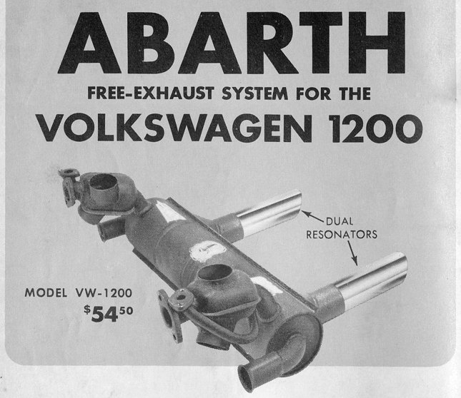
The Italian Arbarth exhaust system. This system proves that you don’t have to go for a separate-tube design to achieve performance.
Käfer – Auspuff 3
By Rod Young
March 1987
A bit of exhaust science this month. You may ask, “Why does a performance exhaust improve power?” The answers are both simple and complex. If the standard system is sized intentionally to restrict power or to keep noise levels low, or, in the case of more modern vehicles, to keep the exhaust gases hot for as long as possible, then simply using a system with larger cross-sectional area will improve flow and horsepower. What it boils down to is flow restriction, or inversely, back pressure.
Whatever you can do to improve flow, by using larger cross-sections (to a certain point), straightening out bends and using shorter lengths of pipe, will reduce back pressure. Back pressure should be minimised because the piston then has less work to do in pushing residual gases from the cylinder on its upward stroke. This explains why a low-back pressure system may give improved fuel consumption also. The reason that confusion arises on the topic of back pressure is that two-stroke motors need some back pressure to work efficiently.
Some of the measures mentioned to reduce back pressure have to be qualified, as they interfere with the other phenomenon which increases horsepower – pulse tuning. This topic is the subject of many learned articles in technical journals, and of more complicated formulas than you would believe. The principle is that, since gas flow in an exhaust system is not continuous but pulsating, there are negative, or lower-than-atmospheric pulses occurring in phase with the high-pressure gas waves. The existence of these negative waves is proven by the fact that if the system has a hole, backfiring will be likely to occur. The reason is that air containing oxygen is drawn INTO the exhaust by the negative pulses, and the oxygen combines with unburned fuel to form an ignitable mixture – which can then burn with a bang.
If these rarefied waves can be timed so that the negative wave from one cylinder occurs at the same time as the ‘overlap’ period of another cylinder – that is, when the inlet and exhaust valves are both open – then the waste gas in the combustion chamber will be pulled through by the pressure difference, so that fresh mixture can more effectively replace the old exhaust gas.
The effect can only happen over a certain engine speed range. Factories usually choose a low-speed range to improve torque over the most-used engine speeds. High-performance engines will have the effect happening higher up in the rev range, since that is where peak power occurs anyway. The way the extraction effect is achieved is basically by varying pipe length. The shorter the pipe, the higher up the speed range the effect occurs. It is important that all pipes be as close to equal length as possible, so the effect is the same for alll cylinders. Cross-sectional areas should also not vary much. If the pipe is too large, velocity drops and the effect is less predictable.
Reduced back pressure and better extraction have another effect – that of lower exhaust gas temperatures. The thermal stress on the engine is reduced, so it can run more reliably, or alternatively a higher compression ratio can be used, meaning more power.
There are two basic designs of high-performance pipe systems – the ‘independent’ and the ‘interference’ type. The independent type is the after-market one fitted nearly universally to air-cooled VW motors. It consists of all the primary pipes leading to one collector. The extraction effect is ‘peaky’, and the system is well suited to racing motors that operate efficiently over a narrow speed range.
The interference type consists of the pipes alternately-firing cylinders (two in a four-cylinder engine) joining together, and these two single pipes then joining further down the line. It is sometimes called a ‘Tri-Y’ design and is preferred where the torque must be spread over a wide range, as on street motors. If you look at a VW Golf exhaust, you will see that in the cast-iron manifold the centre two pipes join and flow into one pipe, as do the outer two pipes. The down pipes then join lower down.
Desirable as it is, there is little room on an air-cooled motor for this to happen, as the alternate-firing cylinders are the front two, 1 and 3, and the rear two, 2 and 4. It has been done – on some American systems and the Australian ‘Sonic’, but in both cases the pipes that join are the wrong ones! A proper Tri-Y system would require pipes crossing underneath the motor, and the existing heat exchangers are out of the question.
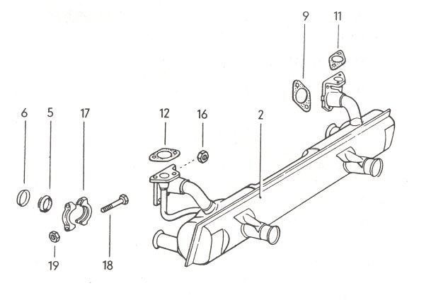
But look at the performance system used on the new Wasserboxer engines where no heat exchangers are required! By the way, this system will fit air-cooled engines if the two flanges are cut and turned around, and it’s a nice thick pipe design, so it should last a long time.
Above is the excellent Wasserboxer exhaust system. It could be improved by making all pipe lengths equal.
The articles I have seen written in American magazines on the subject of ‘exhaust science’ should be called ‘Science Fiction’, as most of them display a distinct lack of understanding of the subject, which is unfortunate when it’s we VW enthusiasts who read it. Even more disturbing, the manufacturers of performance exhaust systems seem to be influenced by the same thinking. If their products work, it’s most likely for reasons other than what they believe.
The first myth that has been perpetuated is that the exhaust gas flowing down one pipe helps to extract the gas flowing down an adjacent pipe at the same time. When you think about it, this is obviously impossible, as the pressure in the pipe is raised when an exhaust impulse blows down, due to flow restrictions that are always there to some extent. If two consecutively firing cylinders share the one pipe, power will actually be reduced, as high-pressure gas in one pipe will prevent extraction in the cylinder experiencing valve overlap.
Witness the Sonic system where cylinders 1 and 4 join, as do cylinders 2 and 3. These are consecutively firing cylinders – there is gas flow from two cylinders simultaneously in one pipe. What’s more, torque is reduced from the two out of four cylinders affected, so the engine is not quite balanced in its torque delivery.
The second myth is that pipes should be arranged so that the firing pulses occur is a circular pattern in the collector, in the interests of better extraction. There is no evidence of this phenomena occurring, and it can be ignored.
If you wish to know more about the real exhaust science, read ‘The Science of Intake and Exhaust Systems’, by Philip H. Smith.
Käfer Auspuff 4
By Rod Young
April 1987
In the last part of this series, I’m going to look at mufflers, tailpipes and how you can put together a system of your own design.
One of the least-understood aspects of exhaust systems is reduction of noise. A muffler has to not only reduce noise, but it should also not affect engine output unduly. It shouldn’t rust out quickly and it shouldn’t be too large or heavy.
There are several design aspects of mufflers that cause a reduction in noise. Firstly, a simple restriction in flow knocks out the high-velocity pulsations. Cheap and nasty mufflers may be very quiet, but have baffles which are very restrictive to gas flow and should not even be considered by you. Secondly, tuned chambers inside a muffler can damp out noise. There are some very complicated formulas for working out the volume of these chambers that I don’t understand, and I doubt that most muffler manufacturers do either. Thirdly, the muffler can contain an absorbent material, for example fibreglass or stainless steel wool. The fibres absorb high frequencies only, giving a ‘sporty’ note to an engine, and these ‘hot dog’-type mufflers have little restriction. Fourthly, if the muffler has two or more alternate flow paths, part of the gas can exit the muffler slightly behind the other part, and peak velocities are lower.
I would recommend ‘Turbo’-type mufflers, if you can find them, and Repco’s premium muffler range also pays attention to muffling efficiency with little restriction. I have used stainless steel oval-shaped straight-though mufflers with good results.
The location of the muffler in the tailpipe system is also critical to noise reduction. Optimisation of this effect can only be achieved by trial and error, but one hard-and-fast rule is not to have the muffler at the very end of the tailpipe.
Rear-engined VWs are especially difficult cars to keep quiet, due to the lack of room available for a long tailpipe system. Many people have fitted dual muffler systems, with good and bad results. The best results can be obtained by running two low-restriction mufflers in series; that is, one after the other, and not in parallel. Dual mufflers in parallel are fairly good for performance, but are hardly quieter than one single muffler.
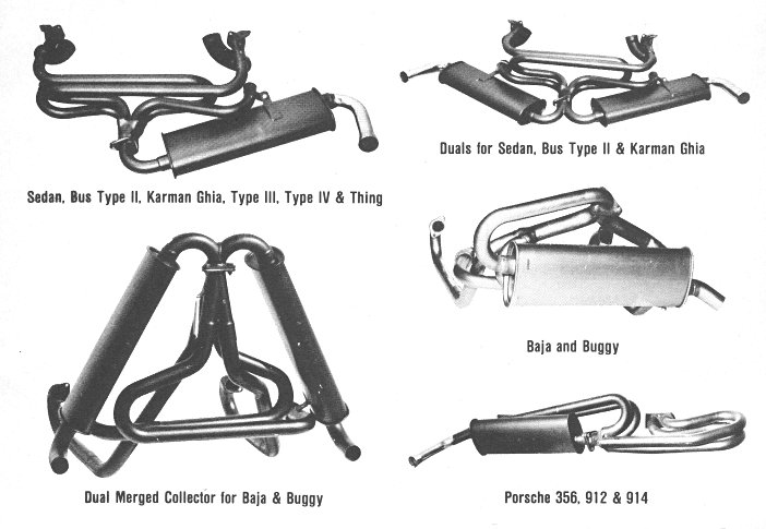
By the way, don’t ever contemplate buying an exhaust system that has two mufflers that run independently, receiving gases from two cylinders only. These are very noisy and are a very inefficient design. There is a variety available for Kombis, and the Beach Buggy ‘dual cannon’ falls into this category also. The mufflers in series, however, make Beetles very quiet indeed, and you can barely hear mine coming (when it’s going at all, that is). You can also make your car look stock by having the exhaust enter through standard-looking tailpipes.
There are some problems that have to be overcome with this set-up. A pipe has to cross over underneath the front of the motor, or under the gearbox. Although it is fairly low on mine, it has never hit the ground, unlike low pipes at the very back of many Beetles. Also, very strong mounts have to be built if these are not to break from the weight of the mufflers. The second muffler, since it runs relatively cold, will rust out quickly unless it is made from stainless steel.
If you have good welding equipment and a lot of patience, you can make your own tailpipe set-up. I suggest you use mandrel-bent tube, since it has the same pipe radius through the bend and can be cut and joined easily. Through experience, I would also highly recommend stainless steel. Sure it’s damned expensive, but when you put days of effort into building a top-notch system, you don’t want to have to do it again after eighteen months. It’s nice to be able to get it apart again too, and looks are very important for some people. And finally, 1¾” (45mm) pipe is of sufficient size for street motors.
Exhaustive Research
By Dave Long
March 1992
Zeitschrift’s captive audience is, I believe, due for a piece on the subject of exhaust systems. I should have dealt with this topic long ago (maybe I have), but only recently did VW exhausts again occupy my thoughts. Here comes the inevitable qualification though: I can only discuss pre-1500 Type 1s, and then only with limited authority. Maybe entertainment can substitute for content!
We have to keep our beasts running, and since no one I know of has come up with a durable substitute, you will have to keep fronting up at the counter of your pet rare spares emporium, compete for the diminishing pool of genuine exhaust mufflers, and pay big dollars in line with supply/demand.
Moving away from the museum end of the VW spectrum, to that intermediate point between the first single-port 1300 and the 1500 Beetle (Australian spec), we find an exhaust muffler which, as to quality of replacements at least, is a disgrace.
This item, part number 111 251 051H and made by Leistritz, usually costs about $95 retail, where $10 would be excessive in terms of time wasted on R&Rs (that’s not Rest and Relaxation!) Throw one on, and it will probably only stay serviceable between annual registrations. Why do we keep doing to ourselves? Because to date there hasn’t been much choice.
Whether this is a process calculated by outfits such as Kadron, in the interests of guaranteed instant repeat business, I'm not certain, but it’s mighty smelly, whatever the answer.
The problem is poor construction, in mild steel with no protection once it has been to operating temperature and cooled a couple of times. They are manufactured in huge quantities of a particularly inferior low-carbon, thin gauge ferrous metal, so a rapid process of destruction begins the moment you start up. This is due in the main to condensation of by-products inside, particularly sulphuric acids resulting from the combustion process, and attack by damp outside particularly when cooling off. Think of a burning wreck; have you ever examined one that has been quite hot, and then quenched by the fire brigade?
Its a similar story with being constantly damp inside (with acids), while temperature jumps from stone cold to rather hot, several times a day, particularly with short runs. On the up side, the more the car is used, the less severe the problem.
Mass-produced exhaust mufflers of this type are made in two parts like shells, which are then folded and spot-welded together. Around the edges, where the halves join, is a particularly good spot for the hydrated ferric oxide demons to mount attacks on your wallet.
These mufflers really are horrible, and should not be acceptable as a disgraceful flaw on an otherwise robust vehicle. If it were common knowledge how relatively little these cost before all the duty and margins are included, it would be no surprise that they are so punily constructed. Of course, you will also usually need new tail pipes, which aren't especially flash either, and the clamping kit, which further pumps up the bill.
There are alternatives in the way of extractors, or one of those Monza 4-pipe systems, but I doubt if they would be all that much better, and unless modified a bit and fitted properly, look pretty ugly to me. Besides, only 40-bhp and 1300 onwards will accept a tailor-made extractor system, and on a standard engine they only seem to increase noise and reduce clearance.
If you know something about pipe bending, and are capable of making a good one of your own, then I salute you, just for starters. I have read that you mustn’t make the mistake of thinking the bigger the pipe, the better it works, because that is not the case. On engines up to about 2-litres, anything over 40 mm is probably a waste of time, as well as performance.
One day, one of us will make the effort to arrange some custom-fabricated stainless VW mufflers, so at least we have a sensible alternative. They won’t be cheap, but think of the long-term savings both in accumulated costs of crappy constant replacements, and the time wasted fitting and removing dead ones.
Ray Black has a beautiful stainless steel split system on his Kubelwagen, which cost him a mint, but it is really special and he will presumably never need to go near it again, except to polish and admire it.
Going back to the 25 and 36-bhp types, there is really very little choice but to seek out an original NOS exhaust - not a pleasant prospect. The single pipe will set you back at least $300, and the later 36-bhp more than $200. Vic Brkovec of Volksbahn had some advertised in issue 13 of VW Power, but then the ad changed. I don’t know if that means he sold all he had.
For those early models, you could once obtain trick exhausts made by Arbarth in Italy. These made a lovely noise and improved performance, but weren’t all that long lasting, due to the same old decay problems of acid/damp. Later, another Italian company, ANSA, made exhaust systems including extractors, but they are no longer available in this country as far as I know.
If you were fortunate enough to locate a proper exhaust of good quality mild steel, befitting your pride and joy, you can improve and extend its life by having it metal sprayed with aluminium. After sand-blasting, the muffler is heated to red-heat and powdered aluminium is then sprayed on, just like paint. The result is a coarse, shiny finish, which is just like textured aluminium. I found it was best lightly sanded first, making the surface easier to clean.
This step at least takes care of the outside. Before fitting, sloshing fish oil around inside could also be of assistance. Most will burn away, usually with copious amounts of smoke for the first few minutes, but it does seem to help and certainly won’t do any harm.
On my ‘56 Oval I am now running an old Lukey muffler from the ‘60s, the one with adjustable tailpipes. Although this has done some miles, it has survived partly through being strongly made, and partly that it has been on the car only a few of the 25+ years since it was made. I admit at one stage though, leaving it out in the weather on a disused ‘60 model for almost two years and it survived well (shame on my slackness!)
Many years ago on my ‘60 sunroof Beetle, the one with the Okrasa engine, I had a Lukey exhaust just like it. To extend its life, I had that one finished in baked enamel, like an old washing machine. That was a success, except for stone chips from bigger lumps of gravel.
Those exhausts were made to last, even though they were not sufficiently appreciated until you couldn't get them any longer. Isn't it always the way! They improved the exhaust note, and were responsible for a small increase in perceived performance due to a freer flow of exhaust gases, and reduced heat.
Unfortunately, as I have said, they don't make ‘em like that anymore.
Exhaust Gas Analysers
By Michael McCarthy
November 1992
As most VW enthusiasts know, the ratio between the fuel and air consumed by a given engine greatly influences its power output Theoretically, perfect combustion would be obtained if the engine burned one kilogram of fuel for every 15.27 kilograms of air.
This figure is based upon weight, not volume. But in practice, an engine requires varying fuel/air ratios to differentiate between maximum power and economy. Generally speaking, maximum power is obtained with a ratio of about 14 kg of air for every kg of fuel, while optimum economy is secured with about 16 kg of air for each kg of fuel.
This aspect is partially due to incomplete mixing of the two components at various stages throughout the RPM range. Therefore, the induction system must incorporate some means whereby the fuel/air ratio is altered to suit the requirements at any given number of revolutions. This takes the form of a carburettor or, more likely nowadays, a fuel injection setup.
One problem immediately becomes apparent. How do we measure the exact fuel/air ratio being consumed? This is obviously important when the owner is seeking maximum power or economy from the engine. The most practical method of measuring the ratio (and how much it changes over the RPM range) is to analyse the exhaust gases.
Before this can be explored, it is necessary to explain the changes taking place when the fuel/air mixture is burnt. The air drawn into the engine is comprised of approximately 78% nitrogen and 21% oxygen by weight. When air is mixed with petrol and ignited, the oxygen combines with the carbon and hydrogen in the fuel, and a variety of products are formed. These consist mainly of water vapour (about 1 kg produced for every 1 kg of fuel burnt); carbon dioxide (CO2); carbon monoxide (CO); free hydrogen (H2); methane (CH4); various oxides of nitrogen, and free nitrogen (which is unburnt because in this series of reactions it acts as an ‘inert’ gas).
The exhaust gas will contain a specific amount of each of these gases, and traces of others as well, depending on the amount of fuel burnt for each kilogram of air. By supplying a little more or less air to the petrol, the content of the gas mixture will be altered.
Having understood this part, another of the gases’ inherent properties becomes important - the thermal conductivity of each different gas. Just as the weight of the various gases differ (in the same way that fluids and solids do), so their individual thermal conductivity, or ability to conduct heat, varies also. Hydrogen, for instance, conducts heat about six times as well as air. Carbon dioxide, on the other hand, will transfer heat only about half as well as air.
From this, you might realise that a ‘rich’ exhaust mixture (that results in high hydrogen and low carbon dioxide content) will conduct heat rapidly, whereas a ‘lean’ mixture (low hydrogen and high carbon dioxide) will not cool a hot object as efficiently. The other gases - oxygen, nitrogen and carbon monoxide - have very similar thermal conductivities to air and will not affect our argument.
If we could determine exact portions of various gases contained in the exhaust, we could accurately measure the air/fuel ratio. We could do this by taking samples of the exhaust gas at given engine speeds, and measuring the weight of the gases contained within. However, this method needs considerable equipment, knowledge and lab technique and is not suited to general auto use. It would be used for stationary and experimental engines in labs, however.
A more adaptable system for our use is based around a ‘Wheatstone Bridge’ electrical circuit, which is simply a circuit with an indicator for varying resistance, shown on a calibrated dial. In a normal circuit the meter would show ‘Ohms’, the unit of electrical resistance, but for exhaust gas analysers it usually reads ‘lean’, ‘normal’ or ‘rich’, thus pertaining to the mixture entering the engine.
The brain of a typical analyser is a small box containing two chambers and coils made from platinum wire one sixtieth of a millimetre (0.017 mm) in diameter. One set of coils is sealed in a chamber that contains only air. The other chamber is connected to the exhaust flow by a small jet. Some exhaust gas will therefore move through the jet and circulate around the second coil.
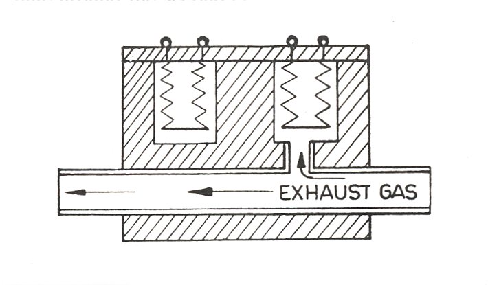
A small potential, usually 12 volts, is set up across the Wheatstone Bridge and sufficient current will flow to cause the thin platinum wires to become hot. Because the coil is exposed to the exhaust gases, any rise or fall in temperature of the coil will change the wires' resistance in the circuit. The variation is transferred to the gauge, indicating the appropriate fuel/air ratio.
The thing to remember is that it is not the temperature of the gases that determines the reading. The amount of heat the gases conduct from the coils is the all-important factor. It is best if the gases are relatively cool, so most analysers use about five metres of hose between the exhaust pipe and the instrument. Where higher performance or racing VWs are concerned, the hose might have to be lengthened to ten metres to ensure the gas is reasonably cool by the time it passes through the analyser.
Here's how a typical tune-up might go. The VW’s engine is firstly allowed to reach normal operating temperature, and the exhaust is checked for damage, holes or leaks. This is because any air sucked into the system would give false readings. The analyser is switched on, allowing the platinum wires to heat up, and the reading is zeroed. The VW is set up on the rolling road, and rubber hose is attached to the exhaust pipe to avoid having water vapour enter the analyser.
The carburettor is then adjusted so that the motor idles smoothly and fairly slowly, and the choke is checked to make sure it is not on. While most analysers are set up with rolling roads, smaller portable units can be attached and the VW actually road tested; the point is that the engine must be subjected to a load. The readings are usually taken as follows:
1. 35 to 40 km/h in top gear;
2. Gradual acceleration between 25 and 50 km/h in top gear;
3. Hard acceleration for about 5 seconds in top and 2nd or 3rd gears;
4. Pulling uphill or against load in top gear;
5. Back to idling speed with the VW at rest.
Due to the time lag between throttle operation and the exhaust reaching the analyser, some 30 seconds must elapse before each reading is taken.
There will be quite a lot of difference between satisfactory readings for various types of VWs and their different levels of modification, but a good operator will quickly spot whether the carb needs adjusting or whether the jets need to be changed. Of course, an exhaust gas analysis would be preceded by other tune-up phases, including checking the ignition timing, spark plug gaps, etc. In some cases, however, a newer car may only need an exhaust gas analysis. One example is when a sticking choke is suspected. The analyser will show when and to what extent the choke is working.
The cost of having an exhaust gas analysis varies a lot between different areas and establishments, but we recommend contacting a Zeitschrift advertiser for advice. An analysis is time and money well spent, not only to ensure peak performance from your VW, but also to gain maximum result from your petrol dollar - and ease air pollution too.
Exhaust Basics
By Brian Austin
February 1993
If you pick up a textbook on car or engine design, it's a sure bet that the entire subject of exhaust systems will be wrapped up in two vague pages. The Club Veedub library for example contains many interesting tech books, but in almost every case a chapter on exhaust systems tell the reader only four things: exhaust systems help keep noise down; they are designed to eliminate back pressure; some systems are better than others; carbon monoxide is dangerous.
Since most VW enthusiasts cut their teeth on facts like these, it was decided to skip the bleeding obvious and dig out the important facts concerning mufflers, extractor systems, ram pipes, power loss and exhaust ‘tuning.’
Surprisingly enough, the evidence gleamed from numerous publications and conversations with technicians are highly conflicting. We are told, for example, that the diameter of the exhaust tubing is a) critical, b) not critical, c) doesn't matter so long as it's big enough.
Consequently, it is generally impossible to reconcile all the data available concerning this hot, humid and exhausting (pun intended) subject, but here at least is the evidence.
Exhaust noise is caused by the impact of the hot exhaust gases, which are thrown out of the engine into the atmosphere. The effect is rather like a locomotive shunting goods wagons; the air is compressed and ‘shunts’ along a series of pulses, which are, of course, sound waves.
The purpose of the muffler is to help reduce the noise level and to allow the air to expand and cool before it reaches the open ends. From a technical standpoint, the exhaust system can be considered in two parts - the actual expulsion of the hot gases from the cylinder and the subsequent reduction in noise level. Both of these facts create problems and the way in which the problems are treated has a very real effect on performance and fuel consumption.
The emptying of the cylinders is critical. The piston pumps the gas out of the combustion chamber, but if anything impedes the flow of gas then back pressure results. If, for example, there is a back pressure of 30 kilopascals (in addition to the atmosphere), then the piston has to pump against this pressure and the evacuation of the cylinder will not be complete.
If the exhaust system were perfect, the piston would pump against atmospheric pressure only. But where performance is really important, some mechanical means must be found of reducing the pressure still further so that an area of low pressure helps extract the gas from the combustion chamber.
The point about back pressure is that it increases with the speed of the engine. Also, at a given engine speed, the loss of power increases very rapidly with the back pressure. For example, if a VW is doing 110 km/h and the additional back pressure amounts to 15 kPa, the loss of power will be roughly 3 kW. If, however, the back pressure amounts to 30 kPa, then the loss will be 6 kW.
The point immediately arises - why should back pressure occur? The answer is that like most things automotive, the design of the exhaust system is largely a matter of compromise. Manufacturers will argue that the loss of 1 or 2 kilowatts in an engine is unimportant when compared with the cost of producing a more elaborate exhaust system. Furthermore, noise is a main consideration and to achieve a quiet exhaust they resort to extensive baffling.
An equally important problem from the manufacturer's point of view is the question of styling. One large company built a successful sedan and then later decided to use its engine and main components in a sports model. When experimenting with the four-cylinder engine, the design department fitted it with four separate down pipes leading to a common chamber. This boosted the power output from 50 kW to 61 kW.
One might expect that the new exhaust system would have been incorporated into the sedan. However, there wasn't enough room under the bonnet to fit it and still leave reasonable accessibility, so the former inefficient system was retained.
Cost factors also influence design. If you look at the average manifold in a production car, the chances are it will be square in shape with sharp corners and cramped passages. A larger tapered manifold with unimpeded exits for the hot gases would do a far better job, but the extra cost (considered in terms of thousands of cars a week) hits the manufacturer too hard.
Even so, the owner can improve most of the original equipment if he has the time and patience. Before considering this side of the question though, let's run our fingers down the terms most commonly associated with exhaust systems.
EXTRACTOR SYSTEMS: Basically, an ‘extractor’ (or scavenger) exhaust system is one in which areas of low pressure caused by the emptying of one cylinder is used to assist in the extraction of another cylinder. Several designs are on the market, ranging from a 4-into-2-into 1 ‘semi-extractor’ at the cheaper end, up to the full 4-into-1 system recommended to enthusiasts modifying their VWs.
This system will produce a measurable 3 or 4 extra kilowatts all the way up the range. The principle involved is that the exhaust gases rushing past the end of one outlet pipe will draw out the air or gas trapped in there, thus reducing the pressure and helping to extract the gases from the combustion chamber when the appropriate valve opens.
A less successful alternative is to use a twin exhaust system with a branch from cylinder one coupled with two and a second branch from three and four (considering the flat-four VW motor here).
TUNED EXHAUST SYSTEMS: Much vague talk is heard about tuned exhaust systems, though in point of fact there are very few cars (other than pretty full-on race cars), which can truthfully boast this feature. The reason is that the power output varies with the length of the exhaust pipe, and can only be tuned when the engine is installed on a dynamometer and the length of pipe varied experimentally until optimum power is reached.
Furthermore, the system must be tuned for a certain engine speed and it will be out of tune at most other points in the RPM range. Thus the exhaust of a racing car is normally tuned to correspond with the maximum power, and in some cases peak power can be raised by as much as 15% when both the induction and exhaust systems are tuned.
Just why this should be can best be explained as follows.
When the hot gases are expelled from the combustion chamber, they strike the air and set in motion a series of high and lower pressure longitudinal pulses - sound waves. This has been understood for at least 70 years, and the early racing designers studied its implication and did their best to take advantage of the areas of low and high pressure caused by the pulses. Despite endless experiments, no one has yet worked out an accurate formula so that the optimum length of an exhaust pipe can be calculated for a given engine at a given speed.
Why is this desirable? Consider first the case of a single cylinder, four-stroke engine with a normal exhaust pipe. Each time the exhaust valve opens, the hot gases are pushed rapidly into the manifold and down pipe, causing the existing air or gas to move in a series of waves. These waves, known more correctly as pulses, move towards the open end of the pipe at the speed of sound in air (generally about 1,200 km/h). This speed varies with the exhaust gas temperature.
The pulses can be considered as areas of high and low pressure. When one of the low-pressure areas reaches the atmosphere, air rushes in to fill the depression. It too has a high velocity and it forms a positive pulse, which then proceeds back up the pipe towards the engine, also at the speed of sound. When it reaches the exhaust valve it is deflected back again, mingling with the other pulses in the same manner as sound blends in the tube of a saxophone.
It is possible to trace the paths of a series of pulses caused by the one opening of the exhaust valve - but since the valve opens perhaps thirty times per second, the task of tracing all the pulses is extremely difficult.
However, the net effect is that a series of high and low-pressure pulses travel up and down the pipe simultaneously. Their nature varies with both the speed of the engine and the design of the pipe, but it can be seen that the ideal condition occurs when a low-pressure pulse happens to coincide with the opening of each exhaust valve. Then the lack of pressure helps to draw out the hot gases.
As applied to an induction system, this is known as the ‘ram’ effect and the pipe becomes a ‘ramming’ pipe.
The ram effect can only be produced experimentally. That is to say, the engine must be attached to a dynamometer and the length of pipe varied until optimum power is shown on the instrument.
Although we mentioned the low-pressure pulses coinciding with the opening of the exhaust valve, the correct length of the pipe is that which makes the peak of the first reflection coincide with top dead centre. In this way, the maximum extraction effect is felt during the period of valve overlap.
This produces a two-fold advantage. First, the extraction of the residual gases encourages the initial flow of fresh fuel mixture through the inlet valve, thus assisting with the induction. Secondly, the presence of fresh mixture in the inlet helps cool the open face of the exhaust valve head.
Advanced studies of the effect on engine efficiency have shown that when the exhaust pipe is the correct length (so that the exhaust action assists the induction), the volumetric efficiency of the engine can be increased by 5% on a normal unit. In outright racing engines, where large valve overlap is employed, the boost in volumetric efficiency is even greater. The net effect in this case, though, is that a percentage of the incoming fuel is sucked out with the exhaust before the valve closes.
Having dealt with ‘extractor’ and ‘ram pipe’ exhausts, we can now look at the more general aspects of exhaust design.
Strangely enough, one exhaust pipe per cylinder is not ideal, even though maximum ‘tuning’ would be possible. Here the optimum length for a high performance engine turning over at about 6000 rpm would be approximately 860 mm. But this imposes a severe design limitation and consequently other avenues have to be explored in the majority of cases.
One solution is where separate pipes from each cylinder are led into a common expansion chamber, also with a common tail pipe. The difficulty here has been that the expansion chamber has to be unduly large to prevent interference between the pulses from different cylinders nullifying the extraction effect.
Manifold design is also critical; we've already noted that most standard sedan manifolds are inefficient because of their obstruction to the smooth flow of the gases. Better solutions are the ‘bunch of bananas’ in which two, three or four downpipes converge to a common pipe.
The purpose of varying exhaust designs is to keep back pressure down to a minimum, and also leave the engine reasonably accessible for maintenance work. The elimination of back pressure is, of course, the most pressing problem.
Mostly it is associated with muffler design. There are three basic mufflers - the baffle, reverse flow and the straight through. The baffle is most widely used on normal sedans. It consists of a hollow shell, with a series of flat baffles that muffle the sound waves.
This type has much to commend it. If the expansion chamber is large enough to allow considerable expansion and cooling of the gases, the engine will be almost inaudible. Cars like the Rolls Royce of the 1930s had enormous mufflers, sometimes nearly as long as two metres, and up to 250 mm in diameter. Exhaust noise was reduced to a subdued burble, but mufflers of this type reduce ground clearance and are somewhat difficult to fit underneath modern compact cars.
Smaller baffle mufflers are therefore more common today but with them goes a reasonable loss of power.
Reverse flow mufflers achieve pressure equalisation and expansion by reversing the flow of hot gases so that the same effect as a large muffler can be had from a relatively small unit To some extent, they can be compared with the action of a pair of prism binoculars.
Straight-through mufflers are generally considered to be the most efficient. Some variations in design can be found; one may be merely a tube surrounded by sound deadening materials. Another has an expansion chamber at one end. A third has an expansion chamber at each end.
The central tube can have either indentations or holes punched to dampen sound waves. Dampening is also effected by fibreglass or steel shavings wrapped around the central tube. Some of the pressure waves pass through the unrestricted core, while others are diverted through the packing, rejoining the main flow at the far end of the muffler before passing out of the tailpipe.
One famous type of this ‘glasspack’ design is the Lukey muffler, originated by Len Lukey of Highlett, Victoria. Fibreglass is used as the sound dampening material and the mufflers are extremely robust in construction. In most cases the noise level is higher than the standard equipment, but the benefit of a reduction in back pressure is equally noticeable.
Fibreglass is, of course, an ideal sound dampener. It is one of the best acoustic and thermal insulators known to industry and is rust-proof, non-corrosive, light and will not burn at normal exhaust temperatures.
The question of exhaust noise is largely personal. I love the bark of a 2-litre Kombi running glasspack mufflers. Some enthusiasts have been known to record the enervating wail of a Porsche 911 exhaust and play it back over their lounge room stereo. I once heard of a Californian company who made mufflers offering varying tones. All mufflers are recorded and the customer is invited to listen to the tapes before deciding on their favourite exhaust note!
Exhaust Wrapping
By Phil Matthews
November 1997
One of the great pleasures of hotting up your air-cooled VW engine is the remarkable improvement in performance. Big cylinders, stroker crank, twin carbs, hottie cam, extractor...you'll never get tired of out-dragging Japanese and Korean bling machines, I guarantee it.
However, once your VW motor is turning out some decent power - say 50% more than stock, which is far from difficult - you'll inevitably come up against the problem of keeping your hot VW motor cool.
I recently found another aid to keeping VW motors cool, this being fibreglass exhaust wrapping. It has always seemed to me that a major source of heating in the engine bay is the exhaust, which lies just under the rear tinware. The hotter your exhaust gets (too hot for ANY heat resistant paint, in my experience) the more heat it radiates back into the atmosphere. This heats the air in the engine bay, which the fan then blows over the cylinders, resulting in a hotter motor overall. If I could cut the radiant heat given out by the steel exhaust pipes (the exhaust itself would be just as hot) then the engine bay should stay cooler.
This is where fibreglass tape comes in. The manufacturers claim it also increases power; that may or may not be true. I'm only interested in its insulating properties.
The fibreglass wrap is available from most performance parts shops, and comes in 30m rolls. It is around 5 cm wide and about 2 mm thick, and will cost around $110 for one roll, which is more than enough for a four-pipe VW extractor.

I removed my extractor, cleaned and painted it, then began wrapping it with the tape. I began at the cylinder head end of each pipe, ending at the 4-into-1 collector. The tape is quite stiff, so once you start the wrapping pull hard and allow about a 2 cm overlap. There should be no slackness in the wrapping at all. It stretches happily around the extractor bends if you pull hard enough, while the straight sections were easy. Once I reached the collector I cut the tape, used a 40 mm hose clamp to hold it, then began the second extractor pipe.
I sat the extractor on my lap. and was thus able to turn it every which way quite easily while wrapping it. If you do it this way, however, don't wear shorts and a T-shirt like I did. The fibreglass will irritate the skin on your arms and thighs and drive you nuts for a week afterwards! Wear long sleeves, long pants and gloves.
Once the four pipes were covered up to the collector, I finally wrapped the collector itself up to the muffler flange and tied it in place with a large 3" screw clamp. I also wrapped the short pipe from the collector to the muffler, but that probably didn’t make any difference.
I then bolted the wrapped extractor back onto the engine, and put everything back together. I was amazed at the difference the wrapping made – the engine was much quieter. I took it for a drive, and noted that the oil temperature stayed a little cooler. That was great, but it was certainly the lower noise level that was the most noticeable change.
The first mistake I made was to exit a steep driveway, when the muffler pipe scraped on the ground and ground away the tape at the bottom. The bits immediately came loose, so I removed them. Luckily it was only the bit from the collector to the muffler, which is not so crucial.
I didn’t discover the second, more critical problem until around a year later. I had enjoyed driving a quieter, cooler VW all that time, and was recommending the fibreglass tape to anyone who listened. Then, one day, the exhaust was suddenly much louder, as if the muffler had fallen off. It hadn’t – all was in place. But it was much louder. I got underneath as the motor was running to have a look. Hot exhaust gas – and noise – was coming from underneath the wrapping, just at the first bend on nos 2 and 4 cylinders. I could squash the whole pipe with my fingers (!)
When I took the extractor back off again, it wanted to crumble to dust in my hands. I took all the wrapping off, and discovered that the steel of the extractor pipes had crystalised, and was crumbling into pieces the size of coffee crystals. The fibreglass wrapping had kept the heat in, and had annealed the steel – changed the actual crystal structure of the metal. Thanks to the wrapping, the steel must have reached temperatures far, far hotter than a non-wrapped tube would ever get. For a low-carbon mild steel, such as extractor tube, annealing temperatures don’t begin until well in excess of 800°C !
So fibreglass wrapping works, but at the expense of drastically reducing the operational life of your steel pipes. They will crumble to dust in short order, due to the much higher temperatures reached. I suspect that fibreglass wrap is designed for heavy cast iron manifolds, or applications like racing where long-life is not a consideration.
Anyway, as they say, you learn something every day. I got a new extractor, and simply painted it with pot belly stove paint. I haven’t tried the fibreglass tape since. But I recommend it – for the short term anyway.
Fix your VW Heater
By Steve Carter
June 2000
It is during the late autumn and winter months that one of the main deficiencies of the traditional air-cooled VW engine design comes to light. The characteristics of the air-cooled engine conspire to reduce the efficiency of interior heating system in almost direct proportion to its requirement! The delight of driving the Beetle during those glorious summer days slowly give way to misery as the weather cools off and the owner becomes acquainted with frozen hands and toes and misty windscreens on anything but the longest journey.
However, all is not lost; the system can be made to operate more efficiently, and improvements made to help you survive the winter months without losing faith in your trusty Beetle. First step is to be fully acquainted with the special techniques necessary to get the best out of the standard system.
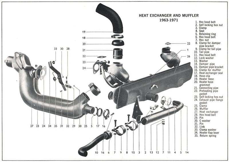
It is as well to understand first how the heating system works. All VW air-cooled models use the same principle but we'll concentrate on the Beetle as our example. The heating system gets its airflow from the cooling fan through the two 50 mm diameter cardboard hoses on either side of the engine, which disappear down through the rear cover plate. These hoses connect initially to the small heater transfer boxes, which enclose the top two exhaust manifold pipes (on standard mufflers only), where heat is transferred to the air flow to take the chill off before it passes into the main heat exchanger units.
These consist of large metal casings, which surround the exhaust pipes from the forward most cylinders. The pipes inside these casings are enclosed in finned aluminium castings in order to transfer as much heat as possible to the passing airflow. From the heat exchangers, the now-heated airflow passes via ducting pipes into the main bodyshell through metal channels inside the sills. Further ducts and vents channel the heated air to the rear footwells, the front footwells, and up through the front pillars to the dashboard and windscreen vents.
On 1968 and later Australian Beetles, the system is controlled by levers between the front seats, either side of the handbrake. The right-hand lever operates cables to open control flaps at the exit from the heat exchanger units. This is basically the on/off switch, and theoretically affords a certain amount of control by altering the position of the flaps. In reality this 'control' is limited by the fact that, with the flaps reduced to slow down the airflow, air is dammed up in the heat exchangers for longer and therefore collects more heat. You either get a strong flow of warm air with the flaps fully open or a weak flow of hot air with the flaps reduced! There is no facility for mixing with cool air to achieve a properly regulated heating system.
The left-hand lever operates cables to control flaps in the rear footwell vents; indeed, the VW Beetle is one of the few cars that has separate heat outlets for the rear seat passengers (even many modern cars don’t have that).
Earlier Beetles did not have these two levers. Instead there was a large knob on the tunnel near the gearstick, which you rotated to move the rear flaps and turn the heater ‘on’. There was no front/rear control. The only other option the driver had was to slide the front vent covers shut (on the floor beside your ankes), which then gave more hot air to the windscreen corners.
Deficiencies in the heating are related to the air-cooling system of the engine. Because the cooling effect of the system is affected by the temperature of the outside air, the engine runs much cooler in winter and produces less heat to transfer to the heating system, just when it is most needed! Also the air being blown into the heat exchangers is cooler to start with and does not warm up so readily.
A secondary problem is that, because the airflow is derived from the engine driven cooling fan, it varies with engine speed. At low speeds the flow is meagre, and at top speed torrents of air are blown through the system. When it does eventually warm up, the system can become excessively hot, particularly at sustained high speed. On older cars, where the front footwell outlets were sited further forward, the driver could suffer a toasted foot if he drove with the heater full on while blasting down the motorway. These vents were moved backwards for 1970 models onwards.
In cold weather, then, the heating system can take a long while to become fully operational, if it does so at all, with all the associated problems of a misted up or frozen windscreen. This is exaggerated if the car is only driven slowly which is all you can do with a misted up or frozen windscreen!
Obviously the system will be even less efficient if there are any faults or malfunctions. There are three main areas to concentrate on.
1. The engine thermostat. This is a bellows device connected via a linkage to control flaps in the bottom of the fan housing. As the bellows warms up through engine heat, it opens the flaps to increase the amount of cooling airflow reaching the engine. If the bellows is damaged or the linkage has jammed open, it will take longer for the engine to reach its normal operating temperature and this will obviously inhibit the heating system.
2. Damaged or missing hoses or leakages in the ducting, will allow airflow to escape either before or after the heat exchangers, thus reducing flow and allowing hot air to seep away.
3. Broken control cables, seized linkages or jammed flaps will prevent proper control of the system.
These are all items that need to be checked out in the autumn months, before it becomes too cold to work on the car. But even with the system in full working order there is still a definite 'technique' that must be applied to get the best out of it.
1. Upon starting the engine from cold, shut the main control flaps (right-hand lever down) and allow the engine to run for a while to warm up. During this stage the engine thermostat is holding the flaps shut at the bottom of the fan housing, so the full blast of air from the fan will come through the heating system. Unless you shut the system, all you will get is a strong blast of cold air until the engine warms up. It may take a little while for the engine to warm up, especially in very cold weather. Scrape the ice off the windows while you are waiting!
2. Before moving off, open the main control flaps (right hand lever) but keep the rear footwell flaps shut (left-hand lever down) and close the sliding covers or shut the flaps on the front footwell vents. This will concentrate what little warm airflow there is on to the windscreen for demisting/defrosting.
3. Once the front screen is clear enough to drive, there are several things that can be done to promote the flow of warm air. Keep the engine speed up by using a lower gear than normal; keep the rear footwell flaps shut (don't tell your passengers that the Beetle is one of the few cars that have separate heating for the rear seat passengers!); and, most important of all, open the windows! Seriously because the body of the car is so well sealed, the warm air cannot flow into the car unless it also has a means of escape. Just open the door windows or quarter vents slightly, but not enough to cause a cold draught. Probably one of the nicest aspects of a sunroof in a Beetle is that you can open it slightly in winter (rain!) to promote a pleasant flow of warm air from the footwell vents up over the driver and front seat passenger.
4. Once the system has fully warmed up, open the rear footwell vents and you can now tell your passengers that the Beetle is one of the few cars with separate heating for the rear seat passengers but you forgot about it earlier on!
There are a number of ways in which you can improve the heating system, some more elaborate and expensive than others. The efficiency of the heat exchangers can be improved by adding extra insulation, thus ensuring that as much heat as possible is retained inside and transferred to the heating air. This can take the form of aluminium foil or tank lagging wrapped around the outer casing. Alternatively, some UK VW accessory shops sell some inexpensive fibreglass insulating jackets, which simply clip in place around the heat exchangers to achieve the same effect.
It is worth noting that the new replacement heat exchangers so commonly sold at VW shops nowadays are considerably less efficient at heating than the original VW components. Most of them are made in South America (a hot part of the world), and they don’t have the solid construction of old German units. Many of them don’t have the aluminium castings inside either; they will be much lighter in weight. For cold climates, it’s well worth searching VW wreckers for a the best set of original German VW heat exchangers.
Some owners fit a smaller diameter crankshaft pulley ('power pulley') for the winter months. This slows down the cooling fan and allows the engine to warm up more quickly. However, it is not particularly simple to fit, and requires a different fan belt. And because it reduces the amount of airflow through the heating system it is somewhat counter productive in this respect. It can also cause your engine to overheat thanks to reduced volume of cooling air.
Another alternative is to fit covers over the engine lid vents to reduce cooling airflow, or to remove the rear cover plate to allow warm auto recirculate around the engine bay. These are all somewhat dubious in that they inhibit the normal functioning of the cooling system and could cause overheating if used on a long journey. At owner's discretion only I couldn't really recommend these practices.
A useful modification is an electric fan to supply the airflow to the heat exchangers. This provides a constant flow of air that is independent of engine speed, and basic through flow is thus greater than that of the standard system at idle. The original fan housing outlets should be capped to prevent loss of cooling air to the engine. A fan which is ideal for this purpose can be found on the Type 4-engined VW vans. It is fairly compact, and has 50-mm diameter outlets that connect easily to the original size cardboard air hoses.
The ideal arrangement is to duct the fan so that it draws air from inside the car, so that warm air is recirculated around the system. A competent DIY person could easily rig up such an arrangement. Complete kits, which operate on this principle, can also be found in the accessory ads in US and UK VW magazines.
The ultimate solution to the heating of the VW air-cooled models is the use of an auxiliary petrol heater, such as those produced by German company Eberspacher. These run independently of the engine, burning petrol in a separate heat exchanger with an integral fan and producing torrents of heat for the interior of the car. Various different models of this heater were originally available from VW dealers as special options on cars for export to cold climates, but apparently Australia wasn't considered cold enough – they were never offered here.
An Eberspacher unit was fitted as standard to UK Type 4 models (411 and 412), some of which had the additional refinement of an automatic timer to switch the unit on at a preset time, before driving off on a cold morning in a nicely preheated car. These Eberspacher units occasionally appear on the second-hand market, and a few technically able owners have adapted them to fit their Beetles. Eberspacher units are still manufactured, primarily for use in marine applications (yachts etc); though purchased new they are rather expensive for the average Beetle owner.
Another option are 12-volt ceramic fan-assisted accessory heater units, available from caravan/camping shops and auto accessory stores. These plug into an accessory socket such as a cigarette lighter socket, and are about the size of a packet of laundry detergent. They give out a useful amount of heat for a small VW, but they are power hungry and can really only be used when the engine is running – or the battery will be flattened in no time.
Experienced VW owners also know the value of wearing an extra jumper, woolly socks in winter, and carrying an extra towel to wipe the windscreen.
Failing all these possible remedies, may I recommend Damart thermal underwear?