
Lubrication
External Oil Circuits 1
Oil Coolers
Oil Circuits and Fittings
Oil Cooler Plumbing and Thermostats
Oil Filter Selection
Oil Sumps
External Oil Circuits 2
A Drop Of Oil
Selecting the Right Oil Cooler Seals
Advice on Changing Your Own Oil
External Oil Circuits 1
By Rod Young
August 1985
When the VW engine was designed, and throughout successive revamping, the factory saw fit to include a crankcase mounted oil cooler, which was necessary to ensure an adequate margin of cooling reserve.
In our efforts to extract more power and reliability from the VW motor, many of us have wished to add an external filter and/or cooler, along with other more esoteric oil related devices. This series of articles will attempt to explain some of the related theory, and to give what are hopefully helpful hints.
Oil Cooling
As a motor develops more power it also develops more heat. In order to operate with the same margin of safety as a standard engine, the heat disposal facilities of a high performance motor need to be improved upon. The generally high ambient temperatures encountered in Australia make this need even more imperative.
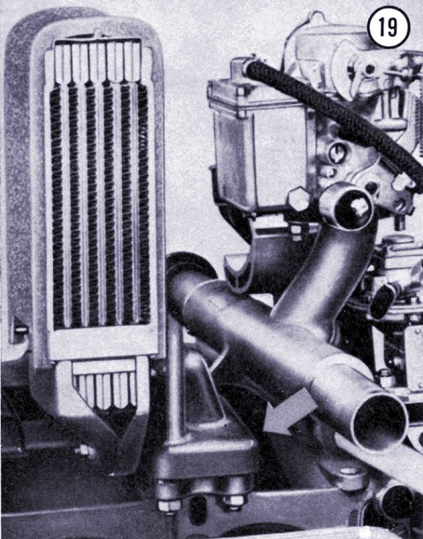
There are a lot of traps for the unwary in installing an oil cooler kit, due to the lack of research by the manufacturers. The type that replaces the standard cooler with one that mounts across the fan inlet actually causes an engine to run hotter.
The first necessary step is to fit an oil temperature gauge, to establish a baseline for later results (why did VW never fit one, or even a warning light, I wonder?) At least now you can determine whether any further measures are required. The ideal temperature range is 80 to 90 degrees Celsius. If you hit 110°C at full throttle up a long hill on the expressway in summer, then something needs to be done. 110°C is the temperature at which mineral oils start to deteriorate chemically and lose effective viscosity.
The best advantage should be made of standard VW components at the engine planning stage. Twin-port motors have a larger oil pump, along with the four-rivet cam. The larger aluminium oil cooler from the Type 3 was placed at the front of the fan housing, so that air heated by it would not preheat numbers 3 and 4 cylinder barrels. Finally, the width of the fan was increased. This revised cooling system works very well, giving a far greater cooling safety margin to a standard engine, and even allow a fair margin for performance modifications. Nothing in this carefully designed system should be altered without a great deal of thought and experimentation, and this includes the thermostat and flaps, which should be left as is for proper warm up and air directional flow. It shouldn't be necessary to mention that all areas of the tinware must be kept sealed, so that no pumped air escapes, and no hot air recirculates, but it is necessary, as this familiar situation is encountered time and time again by unknowing or uncaring owners.
Cooling improvements using standard parts can be effected by installing late Type 3 "cool tin" cylinder air deflectors (part no. 113 119 451), and by replacing the standard cooler with a wider Type 4 unit from a flat Kombi engine. This swap needs a little sheet metal reworking.
There is a good chance that these measures alone will be sufficient to ensure reliability, assuming that fuel mixture and ignition advance, in that order, have been optimised, and these two are extremely important for cool running.
I consider it wise to plan things so that a cooler can be added at a later date, in addition to the standard equipment, if it is found necessary according to the oil temperature gauge. This move may save a great deal of work and expense, not to mention the disadvantages of adding a sophisticated external oil cooler circuit. These disadvantages are, in order of importance: The chance of something going wrong due to the cooler or hoses being damaged, or hoses popping off or deteriorating; the possible need for a bigger oil pump to cope with the flow losses, meaning expense; a power drain from the engine; a greater chance of blowing out filters on cold mornings; the compromising of other systems on the car due to hoses and cooler being in the way; oil leaks, the effect of aerodynamics, the extra weight, the consideration of looks...need I go on?
If you can get away with not using an external cooler, consider yourself lucky.
Next month...for the unlucky, fitting an external cooler.
Oil Coolers
By Rod Young
September 1985
So, you've decided that your new project is going to have an oil cooler from the outset, or you've discovered that oil temperatures in your existing setup are too high. Where are you going to put your oil cooler? The following criteria must be taken into consideration.
There must be plenty of air flowing through the cooler - this is most important. Whatever air can get in must get out again. What you need is high velocity air, and large cross sections in any ducting. Air should not be able to pass around the cooler; it should be sealed so that air is forced through. The best location on any car is right at the front. At speed, there is a high-pressure area in front of the cooler, and a low-pressure area behind, leading to airflow through.
The cooler should be as close to the engine as possible. Oil hoses should be short, to reduce flow and pressure losses. Obviously, on a rear-engined car, this contradicts criterion number 1, so a compromise has to be made. However, it's no use having the hoses short if no flow gets to the cooler, so keep criterion 1 in mind.
On the subject of flow losses, any 90 degree fittings in the system reduce oil pressure by 35 kPa (5 psi) and 45 degree fittings by 15 kPa (2 psi). So, a system with the cooler at the front of the car with numerous fittings will need the oil pressure boosted, which costs engine power and increases the chance of blowing out oil filters on cold start-ups.
Looks...well, this is entirely up to you. Let's look at some of the common places where people put their coolers on VWs with respect to the above criteria.
1. In front of the fan inlet...Good air flow, short hoses and hidden from view, but don't do it as it restricts and preheats engine cooling air.
2. Above the engine lid...Has to be moved fairly far out to get to where the air really flows, and a whale tail helps to deflect air through. Lines are short, looks are a matter of opinion.
3. Above the gearbox...Fair air flow, reasonably short hoses. Hidden from view. A good compromise location.
4. At the front of the car...Best for cooling. Flow restrictions mean a bigger oil pump is needed. Can be made to look good. This is the only place that German tuners ever put their coolers, and Oettinger even got around the oil flow problem by incorporating a belt driven oil pump which operates independently of the engine lubricating system.
5. Behind the air inlet louvres on Kombis...Not much air flow, as air can go around cooler. Heat ends up in the engine again. Short lines and hidden location.
6. In front of engine on firewall...Forget it, does not cool. Short lines and OK looks, but why bother?
7. Underneath engine...Good air flow, short lines and can hardly be seen, but I would prefer to put a cooler in a position where it will stay.
8. On roof...Cools well, fairly short hoses, and looks OK on pure Off-Road vehicles when you don't mind cutting holes in your roof!
I have seen some other locations when an electric fan was used to move the air, introducing much more complexity. The fact that there are several viable options for oil cooler locations shows that a compromise has to be made, depending on which of the three criteria you value most.
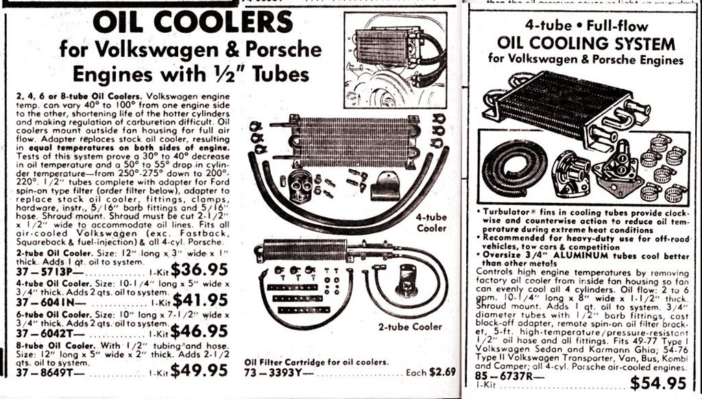
There are several types of oil coolers available. The serpentine type cooler from the Scat type kits is cheaper to produce than the stacked plate type, more prone to damage and is not as efficient as a heat exchanger, as the oil to metal contact area is less. If you have plenty of money, get a Swedish made Setrab cooler. If you don't, find a used Mazda rotary cooler and flush it to remove any grit and sludge. This is always a risk with used coolers. Threaded adaptor fittings are available from Fluid Connectors.
Oil Circuits and Fittings
By Rod Young
October 1985
This month a few words about the proper circuits to use for an external filter...where to get the oil from, where to put it back, and so forth.
The complication in this matter arises only due to the oil pressure relief valve fitted to air-cooled motors. That's the one at the back of the crankcase. Its function is misunderstood by many. It was provided to protect the standard cooler from destruction by a big slug of cold, high-pressure oil hitting it, especially on startup. On some older motors, this sudden pressure wave has been known to snap oil pump drive shafts. The piston of the VW relief valve is pushed downwards and the bulk of the oil flows directly to the bearings, not through the cooler. It is the pressure difference between the inlet and outlet of the cooler that activates the piston, not the engine's absolute oil pressure.
The pressure difference arises due to the flow restriction offered by the cooler, and the restriction is greatest when the oil is cold and viscous. So the pressure relief valve works to some extent as a thermostat also...the oil bypassed straight to the bearings is not cooled.
If you are fitting an external in-line filter, you don't want the VW pressure relief valve to bypass the flow to the bearings unfiltered. If a screw-on filter is inserted into the standard cooler circuit, the much greater flow resistance of the filter will cause the relief valve to open much later, perhaps at high revs and high absolute pressure when the oil is hot, which is when cooling is most needed.
The different piston cups and dirty great springs in those oil cooler kits are necessary to prevent overheating, but they are a compromise too, as a higher pressure drop across the cooler is allowed, which could crack it or blow off hoses, but at the same time, unfiltered oil is allowed into your engine.
The upshot of all this is that, ideally, the external cooler and filter should be on different circuits. The supply to the filter should come directly from the pump, and the return line should be plumbed into the crankcase before the relief valve. This ensures that the relief valve protects the standard, or external cooler.
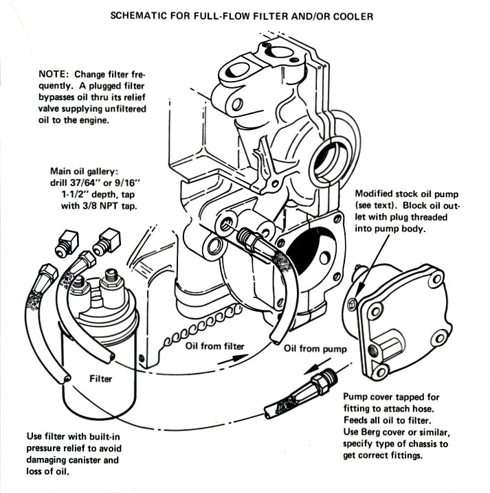
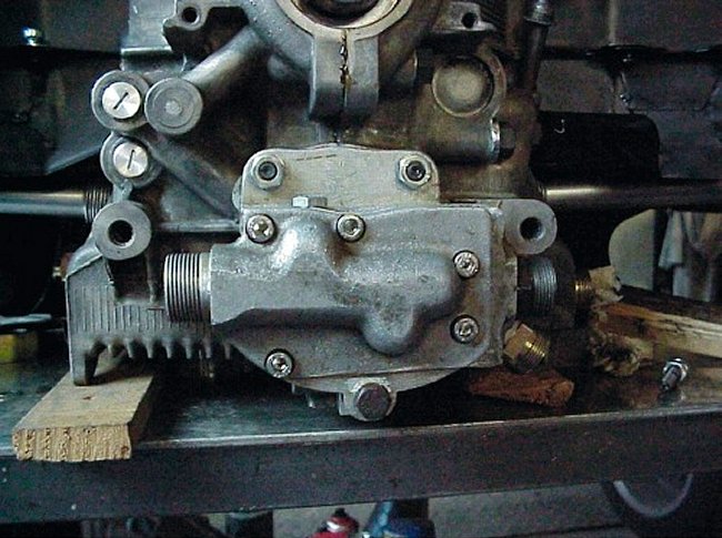
In this diagram, the standard pump cover plate is replaced by one with an outlet fitting, and the outlet port of the pump is plugged. A pump with internal filter would achieve the same end, but since the filter is in a hot air stream the oil must get hotter. However, it saves having to drill and tap the crankcase. Another possibility is a Claude's Buggies "Maxi Pump", which has both inlet and outlet ports on the cover plate.
The correct place to drill and tap the crankcase for the return line fitting is at the plug adjacent the drilling leading up diagonally from the pump outlet. The fan housing on a Type 3 covers this point, and the top of the case must be used.
Oil Cooler Plumbing and Thermostats
By Rod Young
December 1985
If you are fitting an external cooler, it really ought to be controlled by a thermostat. There are two very good reasons for this: If the oil is cooled before it reaches proper operating temperature, about 80 degrees Celsius, the engine will take ages to warm up, more wear will take place and the oil will retain more water, leading to nasty compounds being formed. The other reason is that the cold oil would have to travel further in going through the cooler, causing a drop off in flow to the bearings and a build-up of pressure at the pump. I know all about this, as I have blown up a filter can and blown out the seal a few times when my thermostat was once stuck open.
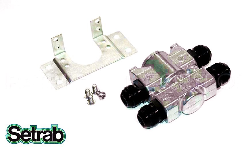
So, having said this, what sort of thermostat should you use and where should you mount it? The Swedish firm of Setrab makes two excellent oil thermostats, one being an in-line design with few hose fittings, and the other a sandwich block which screws onto the oil filter base, and onto which the filter itself screws. This latter type is to be preferred, as only two fittings are necessary, and the whole thing is a lot neater. Another brand is the British Serck in-line thermostat. I have heard that these stick closed, leading to overheating.
The operating principle of both is that a wax pellet capsule, of the type fitted to water thermostats fitted to those other cars with radiators, begins to expand at a certain temperature, pushing on a piston. This piston controls the flow of oil so that the cooler is either in series with the flow when the oil is hot, or is short-circuited when cold.
Because the piston bore is quite large, the piston does not hunt between open and closed, but finds a stable position somewhere between the two, keeping the temperature stable also.
Referring to the diagram, if the sandwich block is used, two hoses will lead off the filter unit and will end up at the cooler. If an inline type is used, either the hose into the filter or the hose out of it can be cut and the oil thermostat inserted "in line", with the other two connections being for the cooler.
Of course one great advantage of using the internal filter circuit for a loop to the cooler is that the standard VW oil cooler stays where it is and operates as it was intended. In this way, any improvements you make are in ADDITION to the factory set up, and fan housing airflow is not disrupted.
There are times when you may wish to use the standard oil cooler circuit for an external cooler. I have seen US advertisements for a sandwich-based block that goes between crankcase and cooler. The block has two fittings for an external cooler, arranged in parallel with the standard cooler. This should work OK, but not as well as what has just been described.
On one of my engines I have blocked up the pressure relief valve and used the external thermostat to control the flow through the standard cooler, which is in series with the external, front mounted one. This was pretty drastic, but you can get away with it because no oil flows through either cooler until it is hot, so pressure related damage cannot take place. Not only that, but that baby warms up within about five minutes, proving that the standard cooler delays warm up. However, I wouldn't recommend the system to anyone else, as it was too much work.
Well, finally now I'm working on a Type 3 engine where the inlet manifold design has not allowed me to use the standard cooler, so I have a standard take off block on the oil cooler flange, and intend to experiment with a wax pellet capsule directly switching the oil pressure relief valve, so that no bulky, expensive external thermostat will be required.
Because of the relatively small bore of the piston, the temperature will fluctuate between two extremes, but the idea has some merit.
Oil Filter Selection
By Rod Young
March 1986
Why did VW never fit a proper full flow filter to Type 1, 2, and 3 engines? The first VW air cooled motor to receive such a thing was the 1700 Type 4 motor in 1969, and the Type 1 crankcase had to wait until 1980, when the 1600 motor was redesigned for the Transporter range. An oil filter early in the life of a Beetle could only have enhanced the car's enviable reliability record. Ford Motor Company found that the addition of a full flow oil filter to their engines resulted in a 66% drop in engine wear. Every VW engine should have one too, for the sake of longevity. Filters will pick up all sorts of things which cause engine wear - small metal chips, aluminium worn away from underneath the valve springs, airborne dust and dirt, contaminants already in the oil and carbon from the combustion process. They will also protect the rest of the engine in the case of any mechanical failure which releases thousands of tiny pieces of metal into the oil.
Replaceable filter cans generally have a pleated paper element inside them, with as much surface area as possible. Oil flows in through holes around the outside, through a one way rubber valve, then through the cylindrical paper element to the centre, where the outlet port is located. Most have a spring loaded relief valve in the bottom which opens when the element clogs with contaminants, to ensure the oil, albeit dirty, flows to the bearings. Unfortunately, the valve can open at other times also, for example when the oil is cold and thick, and some of the particles the element has collected may flow through to the bypass valve. The pressure drop across the filter is important, and should be as low as possible to prevent low pressure at the bearings, especially on startup, and very high pressure between the pump outlet and filter inlet, which can blow hoses off or blow filters up. Theoretically, if a pressure drop such as a filter is introduced to the circuit, the oil pump size or efficiency should be increased to maintain the original oil pressure at the bearings, where it matters.
I previously advised on what type of circuit to use when an external filter is used. It remains only to be said what types of filter bracket and cartridge there are to choose from, as well as some installation hints.
The VW speed shops carry a few types of cast aluminium spin-on filter brackets. The differences lie in the orientation of inlet and outlet fittings. The cartridge these brackets accept is usually from a VW Kombi/Golf/Passat. Shops dealing in Detroit iron might have different types. The hose fittings are usually barbed or flared brass and of 3/8in. NPT thread size. There is a cheap alternative, if you don't mind looking. Chrysler slant-six motors used a cast iron remote bracket, connected to the engine with steel tubes. I found mine on a dumped car in the bush. These brackets have seats which accept the Z9 filter cartridge, which is larger, cheaper and easier to get that the VW one. The bracket also has a thread for an oil pressure switch.
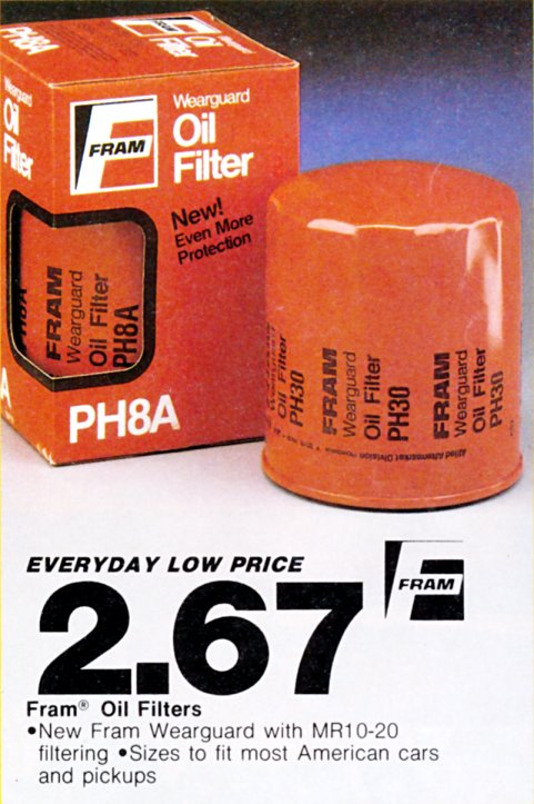
When buying replacement cartridges, I think it makes sense to buy a brand which you've heard of before, such as Fram or Purolator.
There are, and have been, a few spin on filters offering higher performance than the ones you buy at K-Mart. They are either of the throw away variety, or the type where you keep the housing, which may be ribbed to dissipate heat, and open it up to replace the internal element.
Throwaways
Castrol used to make a cotton gauze filter, but I don't know if it's still around.
AMSOIL makes a filter which claims to remove very fine wear particles. They recommend it be used with their synthetic oil.
Removable Element Type
Mecca in the US makes a unit which filters down to 4μm, but which requires no relief valve, having a low pressure drop element with a lesser tendency to clog. It sounds like a good one.
AKT made in Australia, but no longer available.
Trasko uses the same basic principles as AKT, which is that of a combined full flow and bypass filter. Two stainless steel screens filter all oil to 25μm and a small amount of oil is diverted through a cellulose roll, which filters down to 0.5μm. They need a relief valve to divert the oil, and have a pressure drop similar to that of normal filters. I use them because they keep the oil very clean, removing even water.
Installation
Mount the filter anywhere you can get a strap wrench around it, and where it's not in the way of anything else. The bracket should be positioned so that the filter points downwards. There are two advantages to this: firstly it isn't so messy when you change filters, as the oil stays in the can, and secondly, all the air is pushed out. Think about it; if the filter is horizontal only part of the element is immersed in oil. The outlet port is at the centre, and any air above it will be trapped, as it can't be pushed down to escape out the outlet. Once I punched a hole in a can which had been on a car for months, in a horizontal position, while the engine was running. For several seconds, nothing came out the top of the can but air before the oil started escaping. Make sure you don't mix up the inlet and outlet ports, as oil will not flow through a filter that is in reverse direction, due to the rubber flap inside acting as a check valve.
Oberg in the US has designed a full flow filter that works on a different principle than that of spin on types. I have one of these, but haven't used it yet. It has a large square aluminium casing with a very fine stainless steel mesh screen between both halves of the casting. It has a low pressure drop, and no relief valve, thereby assuring constantly clean oil. When the screen collects foreign matter, the pressure drop increases and the screen deflects, closing a switch that warns the driver. The screen is then removed and cleaned in solvent. I've been told that a freshly built engine sends enough wear material to the filter to close the switch in 10 minutes.
The Oberg has a large surface area to dissipate heat, and comes highly recommended.
Oil Sumps
By Rod Young
April 1986
We come now to some uncommon devices that can be applied to external oil circuits in VWs. The two I'm going to talk about are dry sump set ups and the Accusump.
6-cylinder Porsches have always used a dry sump system, and the benefits can apply equally as well to air cooled VW engines. These advantages are: A positive supply of oil, even under hard cornering and acceleration; and the possibility of power gains at very high engine speeds by the elimination of the windage effect, whereby oil is whipped up by crankcase currents covering all moving parts. Competition vehicles use a dry sump system to make engines shorter, but VWs have no bolt on sump anyway, which is why they run into oil surge problems very quickly; that is, when air is picked up by the pump instead of oil.
On VWs, dry sump pumps are usually encountered on midget speed car racers and drag motors. These pumps, by Treuhaft and Autocraft, are very expensive, bulky and require special plumbing circuitry. You can spot them as a long protrusion from the oil pump hole, often driving the Hilborn fuel injection pump as well. A street pump is also made (in Brazil for Claude's Buggies) and it is described as a bolt on, being much more compact, and cunningly designed so that the ports cross over inside to utilise the stock oil pickup tube and pressure feed drilling. I have one of these in my Beetle, and it works very well. The pump contains two sets of gears, the pressure pump and the scavenge pump. The pressure pump takes oil from an external tank (in my case an ATF tank from a semi automatic Beetle, which takes no more oil than the engine sump), and pumps it directly to the bearings, not through any cooler or filter, so that no pressure drop is encountered. When the oil lands in the bottom of the engine, it is picked up by the scavenge pump, whose gears are longer than those of the pressure pump, as it must not allow oil to back up in the sump. The scavenge pump sends the oil to a filter and whatever external cooler system is desired back to the oil tank. High pressures do not build up, as there are no bearings to force the oil through, so hose connectors don't leak as easily.
It is recommended to fit a small 5 inch power pulley with these pumps, as the larger stock sized pulleys would be fouled by the larger pump. I got away with using a normal sized power pulley by spacing it out and machining the inside rim. The scavenge gears are 26mm and the pressure gears are 21mm, which is stock length, but it gives good oil pressure as there is not restriction between it and the bearings in the form of a filter or cooler.
A bit more plumbing is necessary for the tank, but no drilling and tapping of the crankcase is needed. I can corner as hard as I like, and never run out of oil pressure.
All air cooled VW engines, by the way, need some form of oil surge protection, and this can be achieved by extending the pushrod tubes so oil doesn't flow into them as readily, baffling the sump, or fitting a deep sump with extended oil pickup. Extended sumps are very reliable, except when they hit things on the ground.
The high-tech approach to preventing oil surge is to fit an Accusump. This contraption consists of a floating piston inside a cylinder, one side of which is air under pressure, and the other side of which is connected to oil under pressure from the engine. When high oil pressure is present, the cylinder fills with oil, compressing the air on the other side of the piston. If the oil pump picks up air, the pressurised oil is then sent to the bearings, minimising the size of the air bubble which must pass the bearings. As an extra bonus, the bearings can be pre-oiled before startup, as the cylinder is fitted with a ball valve or solenoid valve. This valve is shut while the engine is still running, to store oil in it under pressure, and opened before start up. It's enough to turn the oil pressure light off. Engine wear is thus greatly reduced. Less oil can be run in the sump, without running into surge problems, so windage at high engine speeds can be reduced. Unfortunately, this great gizmo can, to my knowledge, only be obtained in the US.
External Oil Circuits 2
By Rod Young
June 1986
In this episode we are going to look at how to attach oil hoses to all the fittings you are using.
The simplest and cheapest way of doing so is to use flared or barbed fittings and hose clamps, otherwise known as jubilee clips. Often accessories such as oil cooler kits come with these included. They are very straight-forward and have the further advantage of being short, so that they can be got into tight spots. However, there are some faults with this type of fitting which makes them less reliable than hydraulic hose ends and fittings, which is the other alternative. It's not unknown for hoses to blow off with high pressure surges, and I've had a high quality hose fail internally after being clamped to a barbed fitting. Every time a hose clamp is unscrewed, you find that the hose is crushed, so you should really cut that bit off every time you do it up again.
Hydraulic hose ends are the reliable, but certainly more expensive solution. Vehicle manufacturers use them, usually the permanently crimped variety. Hose ends are available which you can re-use if you wish to change the length of a hose. The extra reliability with hose-ends comes from the fact that they screw on with big threads, so you can really tighten them up, and that the seal is achieved by the use of a wide seat. 45 degree and 90 degree fittings are available, and these can be fixed at any angle, as they swivel before tightening.
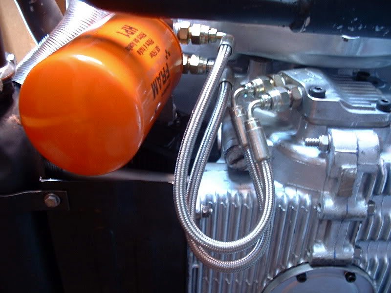
Several types of hose are available; they will all handle the pressure that an engine develops, but make sure the hose you choose can handle 150°C. You can get braided stainless hose, but it is definitely over-engineered for our application. Most people only get it for the looks anyway. Likewise, there are numerous hose end designs; I suggest that the push-on type will cover your requirements as it is very short and less expensive than the elaborate screw-together type. Don't ask me why the hose simply doesn't blow off those things, but I assure you that they do stay together.
Picking the adaptor fittings and proper thread specifications may prove to present some problems. You will encounter terms such as SAE, JIC, BSP, and perhaps DKL (German spec.) These letters describe the type of thread and seat used in the hose end connection. The first constraint is the hose diameter, which must be at least 1/2-in. internally for good oil flow. A half-inch hose will require, for example, a 9/16, 3/4 or 7/8-in. thread if you choose JIC hose ends. 7/8-in. is getting a bit big, by the way. The choice of thread/seat design is up to you, but is determined to some extent by the availability of adaptor fittings, which of course have a different thread on the other end to screw into your oil filter, or crankcase, or whatever. For example, can you get a 3/8 NPT by 3/4 JIC nipple...? Yes is the answer. I warned you it would be complicated. Whoever is selling the parts to you should be able to advise you well.
The final thing to remember is that the hose end seat will seal best if you use a teflon sealing compound, which is a very gooey substance in small bottles. Do the job the professional way and you won't regret it.
A Drop Of Oil
By Rod Young
October 1991
A drop of oil can make a big difference. There is a not-so-obvious problem with those electronic ignition systems which promise reduced engine maintenance. Sure enough, they deliver what they promise, but they usually work so well that you are encouraged to forget about the ignition system altogether!
This has been the case with me, but neglect has finally caught up. At the same time as you’re expected to check the dwell angle and timing - every 10,000 km - (which I haven't done for about three years because of a transistor-assisted ignition) you’re also expected to lubricate the distributor. You should add a few drops of oil to the felt wick on the centre shaft, under the rotor. If you have points you’re also supposed to oil the pivot pin of the points, and grease the cam on the shaft.
The drop of oil on the centre felt wick is what concerns us here. Why is it needed?
The centrifugal advance built in to these distributors requires the breaker cam, the square bit with rounded off corners in the middle of the distributor which opens the points as it spins, to turn clockwise as engine rotational speed rises. I’ll mention briefly how, but not why: two weights at the base of the distributor pivot and swing out as the shaft spins, communicating their motion to the upper part of the shaft, which is free to move with respect to the main distributor shaft; or should be, if it has been getting its drop of oil.
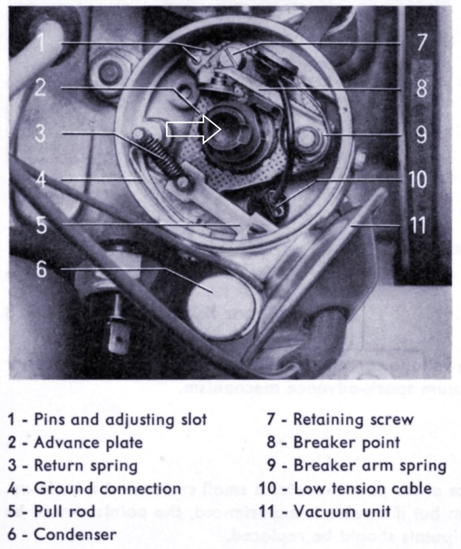
If you lift off the distributor cap and give the rotor button a clockwise twist, it should snap smartly back under spring tension to where it was before you started. If it doesn’t move at all, then it could be that you own a mid ‘60s Volkswagen that didn’t have the luxury of centrifugal advance; a 16-valve Golf, or a newish car with Digifant engine management.
Or it could be that you don't, and it’s stuck. Or else it might twist, but stickily, and not snap back very well.
This last case describes what was happening on my Type 3. In practice the centrifugal advance wasn’t working until the revolutions were so great that the stickiness was overcome and it got past that bit. Now that I come to think of it, for a long time that car was really sluggish off the mark, then sort of came good at around 2000 rpm.
The obvious cure for shafts that have gone sticky is to remove, lubricate, replace, and promise yourself you’ll put a drop of oil onto the wick in future.
To get to the nitty gritty, firstly remove the distributor from the car. Take the point plate off the distributor, then try pulling the shaft off. It won’t come, of course; you’re doing this because it’s stuck. My trick here is to tighten a small hose clamp around the top of the shaft, wrap the jaws of a vice around it, then tap the rim of the distributor gently so that the offending item is left in the vice.
I've come across quite a few vehicles which had been getting no advance at all, and whose owners were either wondering why the car was such a slug or had bumped up the static advance so it would go half-decently.
In one case I noticed that at part-throttle the car would go better than at full-throttle; obviously the vacuum advance was helping it along until there was no vacuum.
A friend of mine has an interesting story to recount. A neighbour, who was a fairly old bloke, gave him a quite decent 1974 1600 Kombi, apparently because my friend already owned an older Kombi in poorer condition, and the newer one didn’t go very well. I diagnosed the problem to be what this article is all about, and did the unsticking thing, and my friend was amazed.
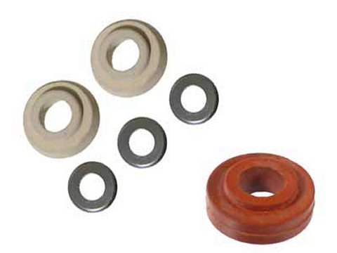
Selecting The Right Oil Cooler Seals
By Lance Plahn
April 1998
The task of selecting the correct oil cooler seal to suit both your crankcase and cooler, can be difficult one as there are three different types of cooler seals in a standard VW engine overhaul gasket set (plus another type available which is not supplied in the gasket set). There's also the problem of obtaining seals from your parts stockist, especially if you don't take a sample or don't know what you need. The problem occurs most frequently when fitting the black tin oil cooler to Type 1 and 2 motors, as there are three different types of seals available to do the job.
During August 1969, Volkswagen increased the size of the oil cooler aperture in the crankcase and in the cooler itself from 8mm to 10mm, which resulted in two different crankcases - one with 8mm oil cooler holes, the other with 10mm - and two different styles of tin oil coolers.
To enable the then-new crankcase to be used with engines manufactured before July 1969 without having to install the new oil cooler at the same time (and conversely, the new oil cooler to be fitted on an older crankcase), a conversion oil cooler seal kit was released.
This kit is comprised of two cooler seals and a number of spacer washes (tinware washers). The seals are tapered on the inside from 8mm to 10mm and have an outside ring around the middle to separate the smaller outside diameter from the larger outside diameter end. These seals are usually made from a green material, although aftermarket seals are of a white material.
As for the differences between the two oil coolers, the early unit obviously has 8mm oil holes - with a small recess around the holes - and is flat across the bottom and mounting points. If you mount this cooler on a crankcase without the seals, there will be no gap between the cooler and the crankcase. This cooler was fitted to the 1200 and 1300 motors.
The later cooler has 10mm oil holes, with a larger surrounding recess. There is a raised section around the two mount bolts and the mounting bracket on the side is located further down, making the cooler sit higher. This means that when you mount the cooler on the crankcase without the seals, there is a gap between the cooler and the crankcase of approximately 3mm. This cooler was fitted to the 1500 and 1600 single-port motors.
So, which seal do you use to fit a tin oil cooler? If using an early crankcase (8mm holes) and an early oil cooler, use 2 x 111 117 151 seals. If using a later crankcase (10mm holes) and a late oil cooler, use 2 x 021 117 151 seals.
But, if matching a late crankcase with an early cooler, use a 111 198 029 conversion seal kit. The wider end goes into the crankcase, with the narrower tapered end fitting up to the oil cooler. Using the three washes supplied with the kit, place one under each of the mounting bolts between the crankcase and cooler.
When mounting an early crankcase with a late oil cooler, again use the 111 198 029 conversion seal kit. This time, the smaller tapered end fits into the crankcase and the larger end to the oil cooler. The washers supplied with the kit are not used in this instance.
1600 twin-port Beetle and Kombi motors are fitted with an aluminium oil cooler, which bolts to a stand-off housing, retained by three 8mm studs to the crankcase (this setup should use 4 x 021 117 151 cooler seals). To successfully mount a tin cooler to these crankcases, remove the 8mm stud and replace it with a stepped 6/8mm stud (the one used to repair stripped oil strainer plate studs). You then have to sleeve-down the other two 8mm holes and you can use and old 1600 pushrod for the job. Cut one end off and enlarge the internal diameter by drilling out to 6 mm. Then cut off two 10mm lengths from the pushrod - these are the sleeves.
One of two things can happen when incorrect cooler seals are installed, regardless of the motor/cooler combination. Firstly, after a settling-in period, the seals can start leaking. This is due to the cooler being tightened onto the cooler seals, squashing them. Seals that settle or lose tension result in a cooler that becomes loose on the crankcase. The bottom of the cooler can also be dented. When the correct seals are used, the cooler is tightened against the crankcase and the cooler seals are lightly compressed between the cooler and crankcase.
The other problem is that the hole in the cooler seal reduces in diameter, causing a reduction in the oil flow to vital components -this could result in your motor failing prematurely. This situation is hard to detect.
Now that you have made the correct cooler seal choice, all that remains is to mount the cooler to the crankcase. But, before doing so, give the cooler a good visual checkover. Look for external damage, which could cause reduced oil flow in the cooler, or damage that could leak oil. Check the mounting tab on the side of the cooler to ensure that it is not fractured or even broken off, as this could result in only two bolts retaining the cooler to the crankcase. Make sure that the cooling air passage through the cooler is free from any abnormal restriction - examples of which include dirt, other foreign matter or the cooler tubes being expanded into the air stream, the latter example possibly restricting the air flow through the cooler and to the number three/four side of the motor. If new cooler seals are fitted and are correct, but there is a oil leak from the cooler area, it is possible you have a cracked crankcase, and that's another story.
Advice on Changing Your Own Engine Oil
By Lance Plahn
June 1999
This is hopefully the first in a series of ‘How To’s’ on simple maintenance and necessary tasks required in keeping our VWs on the road in a safe, trouble free condition.
Now before we get into the nitty gritty of changing the oil, let's first cover a few basics.
Oil companies refine or buy crude oil, then add their own blend of ingredients, sometimes over forty kinds in fact. Some chemical additives include Oxidation Inhibitors, Detergents, Viscosity Index Improvers and Anti-foam Agents. These additives break down, necessitating the need for an oil change. It should be noted most oil companies recommend the oil is good for 10,000 km or six months (after the oil first reaches operating temperature). There are basically three types of oil – Recycled, Mineral and Synthetic.
Volkswagen recommended 30w oil for the early air-cooled engines. Heavy weight oil (ie. a higher number) is too thick for the small oil cooler holes, resulting in an increased oil temperature at the cooler instead of any cooling effect. An oil cooler is fitted to aid cooling of the engine; the oil absorbs heat from hot parts it comes in contact with, then releases this heat at the oil cooler. Some oils, such as those suited for turbo use are not designed to work this way – they resist heat instead. Modern multi-grade Mineral oils are good for the air-cooled engine, and either Mineral or Synthetic oils can be used for water-cooled VWs.
Now with all the environmental laws in place it is illegal to pour waste oil on the ground. So bottle your waste oil and take it to an approved disposal station. There is a good drain bottle on the market suited for this job; it is a square plastic bottle, with one side funnelled in with a removal bung in the centre. Drain the oil into the bottle, refit the plug and you now have a carry bottle. When draining oil, wear gloves and protective clothing, as waste oil does contain toxic chemicals. If working under a raised vehicle, ensure the wheels are chocked and approved safety stands are in place.
The tools and parts listed below are primarily the ones needed to perform the oil change on a 1600cc air-cooled engine. Other models such as the larger air-cooled Kombi, and water-cooled VWs require different parts and tools, but the task is still very similar.
* Workshop manual on your model - take a few minutes to read it before performing any repairs. This will give an idea on how to approach the job and you may pick up some tips along the way.
* Drain tin/container of adequate capacity
* Solvent - to clean the oil strainer (air cooled only), not petrol or kero as these are hazardous chemicals. Try using a can of carby cleaner, but use gloves and safety glasses.
* Oil (and filter if fitted, plus a filter removal tool, used only for removal)
* Oil change kit (suggest good quality, the cardboard ones tend to leak)
* 10 mm ring spanner or socket
* Jack, wheel chocks and safety stands
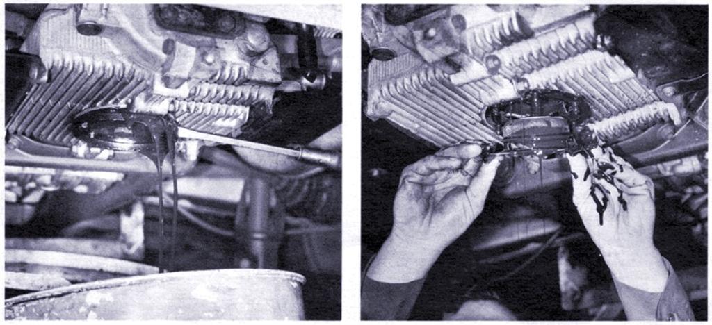
Now to changing the oil on 1200 to 1600cc engines, be warned it is very unlikely you will drain every last drop of oil, hence it makes little difference whether the oil is hot or cold. Hot is better as it drains faster and more completely, but hot oil (and a hot engine) is a safety hazard. If cold it will take a little longer.
Raise rear of vehicle to suitable height to access the sump plate if required, and put chocks and safety stands in place. Place drain tin under sump plate and undo the six sump plate retaining nuts. Undo the ones furthest away from you, then slowly release the last nut (closest to you). Oil will exit from around the plate. Remove sump plate and oil strainer. If time permits allow approximately one hour to drain. You can do other service items to the vehicle in this time.
Clean sump plate and oil strainer, renewing any damaged components Remove any trace of gasket stuck to the engine case. Check the sump plate is not bent or distorted around the six holes, which can result from not using the copper washers. This can cause an oil leak. File the raised section level again or renew sump plate. With a clean rag, wipe the sump hole in the engine clean and dry.
Refit oil strainer and sump plate with new gaskets. Fit the first gasket, then the strainer, then the second gasket, and finally the sump plate. Remember to use the small copper gaskets, and the genuine VW dome nuts to reduce the possibility of an oil leak. Do not over-tighten the nuts.
Remove the oil filler cap. Check the cap gasket as they occasionally require replacing. Pour approximately two and half litres of new oil, slowly, into the engine. Check the dipstick and top up if required. Start the engine, ensuring the oil warning light goes out within a few seconds. If not turn off and check for problem. Check for any oil leaks. Re-torque the sump plate after the engine has obtained operating temperature and has cooled down, as new gaskets compress, resulting in the nuts losing their tension slightly.
You may have noticed no reference has been made to the drain plug in the sump plate. Volkswagen dropped this idea in latter years, probably due to oil being changed only from the plug, instead of removing and cleaning the oil strainer and sump plate, which is an essential part of the job.
As a result of many oil changes and over-tightening the sump nuts, damage can occur at any time, namely stripped nuts, so keep a few on hand as spares just in case.
The retaining stud often strips the thread in the crankcase. There is a stepped stud available from VW workshops to repair this problem. It is 8 x 1.25 mm on one end and 6 x 1.00 mm on the other. Remove old stud. Drill the stripped hole, using a 6.5 mm drill. Using an 8 x 1.25 mm tap, cut a new thread. Clean all metal shavings from the engine. Fit stepped stud, using Loctite to keep it in place if desired.
If your engine is fitted with an external oil filter, such as twin carb Type 4-engined Kombis, any water cooled VW or Type 1s with an aftermarket kit, it is advisable to change the oil filter at the same time (and at every oil change). Place a drain container underneath, and remove the filter by screwing anti-clockwise. You may require an oil filter tool for this job, available at most auto parts stores.
Wipe the oil filter housing clean, and smear some clean oil on the oil filter sealing
Ring. This prevents the seal from grabbing on contact with the mating surface.
Buy a good quality filter; genuine VW ones are better than Kmart filters. Prime the new filter with oil, which will take a few attempts as the filter absorbs the oil. Fit new filter, tightening by hand, and a further two thirds of a turn after the filter makes contact with the sealing surface. Start the engine, check the oil light goes out. Check oil level and top as required. Check for any oil leaks underneath and around your motor.
Other maintenance items required at this time could include cleaning the air filter; checking fan belt tension and condition; checking and adjusting all fluid levels, including brake, washers, battery, gearbox and coolant. Grease front end. Adjust brakes. Check and adjust tappets. Check all lights. Check tyre pressures.
But that's another story for the future. Good luck!