
Fuel System
Fuel Pumps and Other Matters
Quiet Carbs
Well-Balanced Carbs
Short Cables
The Last Word on Float Bowls
A Whole Lot of Hot Air
Racing Fuel Basics
Fuel Injection and Engine Management
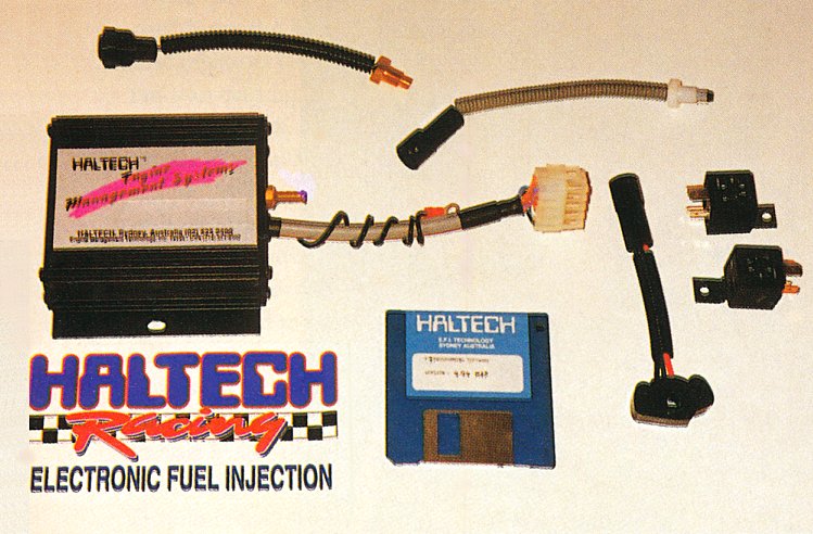
Haltech Programmable Fuel Injection
Mixture Screw Blues
Big Bad and Beautiful
Leaded or Unleaded
Automatic choke adjustment
Octane Number Explained
VW’s FSI injection system
What fuel is safe to use in my VW?
Fuel Pumps and Other Matters
By Rod Young
July 1987
Have you ever thought of replacing your mechanical gem, the Solex by Pierburg/Neuss item screwed to the top of your engine, with an electric fuel pump? The advantages of such a step are numerous, but like everything else, it's not as easy as it sounds if it is to be ‘engineered in’ properly.
I mentioned that there were advantages: how about the fact that genuine replacement fuel pumps will relieve your wallet/purse of $125 or more? Of course, there are always the Brazilian replacements, but a few things have been known to go wrong with them, like total failure, and the fuel pump is one thing that you want to be reliable. Anyway, did you buy a well-designed, reliable (Australian-made) German car, or a Brazilian one?
A fuel system fitted with the standard fuel pump can suffer from the phenomenon known as ‘vapour lock’, though Volkswagens are less prone to this than other cars. What happens is that the fuel in the inlet line to the fuel pump boils, due to the heat it has picked up from the hot engine pieces surrounding it, and the pump will not seal well enough around hydrocarbon gases to pull liquid fuel through, hence no fuel delivered to the carburettor. Now you know why the pump has a Bakelite spacer underneath; it stops crankcase heat from conducting into the fuel. If your car gets the symptoms of vapour lock one hot day and you have to be at a wedding in ten minutes, one thing that you can do to the fuel pump that might work is to piss on it. This operation is considerably easier on Beetles than nearly any other car. (But officer, I was only trying to start my car!)
There are two reasons why mechanical fuel pumps are prone to vapour formation. Firstly, the fuel pump picks up heat, and the fuel lines are necessarily routed close to the hot engine. Secondly, much of the fuel line is under a slight vacuum, as the pump has to suck its supply of fuel from the opposite end of the car, often through the added restriction of a filter, which lowers the pressure in the fuel line even more. Didn't they teach you in school that a liquid boils at a lower temperature when its pressure is lower? Of course they did. Why didn't you listen? So if you move the fuel pump to the front of the car, underneath the fuel tank (there's no point in moving the mechanical pump, because there's nothing up there to drive it, so it must necessarily be an electric one), all the fuel lines near the hot engine run at elevated pressure, and the temperature at which the fuel will boil is a lot higher.
Back to filters. I stated if the fuel pump has to suck through a filter, the pressure on the suction line will be lower. There is no reason why the filter has to be on the suction side of the fuel pump. Yes there is, I was lying, there is one reason - the fuel pump then gets a supply of filtered fuel. But if there is any chance of vapour lock, it's better to place the filter between the pump and the carburettor.
The Wolfsburg engineers, in all their wisdom, have solved the problem on their newfangled water-pumpers by fitting a small bleed back to the tank off a T-piece near the carburettor inlet. The amount of fuel going back to the tank is not enough to worry about - it makes the pump work slightly harder, that's all. The important thing is that any vapour trapped in that line is shot back to the tank and the fuel pump stays primed with wet stuff. And they can even afford to have the filter before the fuel pump for its own protection. It's a joy to realise the intricate details of Good Design in the microcosm of the engine compartment. Don't fool with any factory-designed thing like this unless you have as much theoretical knowledge or practical experience as the designers, or are prepared to learn from your mistakes. I know I don't. Whew, glad to get that off my chest.
I have even asked myself if those same Wolfsburg engineers, or their older colleagues some years previously, designed in vapour lock as a backup system for the engine's well being. I will explain myself. On more than one occasion (twice, in fact) I have come to the aid of Volkswagens with overheating while driving along the road. Not to the aid of the owners; they deserved to be shot, but to the aid of the Volkswagens, because I have more respect for them than people who work on cars without knowing what they're doing (do you stop when you see a VW on the side of the road?) On both occasions, the cars had vital pieces of cooling tin or rubber missing, and the engines had become so hot that the fuel in the lines near the engine had vaporised. Undoubtedly, these two cars were saved from the destructive ‘engineering’ of the owners by an inbuilt desire for self-preservation. The moral is, if you don't know what you're doing but still have respect for your VW, leave the original fuel pump on it and don't fit an electric one, or have someone who knows what he/she is doing perform the operation and do all your work for you.
There are a few more advantages to having an electric fuel pump which I have neglected to tell you. That "toc-toc-toc" or "mrrrrrrrr" is very reassuring, and is a powerful diagnostic tool. An electric fuel pump lets you know when it's got no fuel to pump, either through lack of the vital substance in the tank or through the aforementioned dreaded vapour lock, rare as it is with electric pumps. You can't hear if a mechanical fuel pump is working at all. If your car won't start, an electric pump will either make the right noises and you can disregard it as the source of problems, or it will tell you that it's not working. Another advantage is that starting the engine under any conditions is easier, as the carburettor float bowl (s) are always topped up before you turn the motor over. Do you know how long you've got to turn the motor over if your tank runs dry? If your battery is at all dodgy, it might make the difference between starting and not starting. If you are the type who has the carburettor(s) out every weekend, you will welcome the facility of instant priming.
One further trivial advantage of an electric pump is that you have ever-so-slightly more room on top of your engine and it's easier to remove and install the engine (two advantages). Don't be tempted to vent crankcase fumes up to a breather through your piece of hacksawed plate that you're using as a block-off for the fuel pump hole. So much oil gets thrown up there that you'll wish you hadn't. I know this.
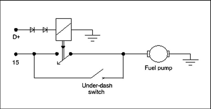
I stated at the beginning that an electric fuel pump should be engineered in properly. One detail which I see as vital, but which many others do not, in the interests of less work/thought/effort, is to make sure that the pump cannot keep running when the engine stops. There are two convincing arguments for this: if your car is badly damaged in a collision, you do not want to be pumping fuel all over the road. I know Subarus are designed that way, but that's no excuse for poor design. American manufacturers of fuel pumps recommend using a switch activated by engine oil pressure. Alternatively, you can let your generator or alternator "D+" supply turn on a relay supplying power to the pump. Both good ideas, but the switch is hard to get here, and with both set-ups you lose the advantage of instant priming. To get instant priming, all you need do is put an unobtrusive momentary action switch under the dash for those rare occasions when you may need it. I prefer the relay solution, as it is easily done and provides the second of my convincing arguments. What if you break or throw a fan belt in your Beetle? If you don't see the warning light, you have a matter of two or three minutes (? I don't really know) before your engine fries. If the belt-driven generator/alternator (strike out whichever doesn't apply) is powering up your fuel pump, within thirty seconds the engine will have stopped from fuel starvation. Remember what I said about an engine's survival instincts? Design them in! Look at the diagram for the layout of such a system. (Cars with an alternator may require the addition of two diodes to drop residual voltage down enough to switch the relay off).
As is only to be expected, the factory has designed the ultimate solution, which is electronic and used on electronically injected cars. On Type 3s and 4s, the fuel pump is turned on for a few seconds when you switch on the ignition, restarts as soon as the distributor turns and switches off when the distributor stops turning. I have designed an electronic circuit of similar concept for my (carburetted) Beetle, and it works just great. On L-Jetronic Kombis the fuel pump is switched on by the starter motor and switched off by the air-flow sensor flap closing.
Which pump to use? Well, I have experience with two, but there are, of course, others. I have used the Subaru pump, which is the old S.U. design but better made; and the Type 3 fuel injection pump, which is a little masterpiece.
I have long ago removed the foreign, stuttering Subaru noisemaker from my Beetle. Some people take off the rubber mounts and bolt the pump direct to the body - it sounds like somebody is throwing rocks at the car from outside. But they are pressure-regulated, cheap second hand, readily available, easily fitted and reliable. They have the dubious design feature that each pulse delivers a measured quantity of fuel from the tank. I took advantage of this feature once and designed an electronic circuit that counted the pulses from the pump and gave a readout of fuel used on two seven-segment LEDs. It was more accurate than any trip computer I've seen. For the record, one litre of fuel requires 924 pulses from the pump.
I now use a Type 3 fuel injection pump, because I'm much happier having a Volkswagen part on board. You're not supposed to be able to use these for a carburetted car, as they're not pressure regulated. These pumps will hold whatever pressure you'd like to keep on them and will flood any carburettor needle valve known to man if the pressure is not relieved somehow. What I did was to bleed back a small amount of fuel to the tank through a 1.5mm orifice. That required brazing a fitting to the bottom of the tank, and this idiot set his hair on fire in the process. The fuel pressure will still vary depending on what the carburettors take, and the orifice should be set so that at full throttle/max. revs the pressure stays high enough to supply the carbs. Pressure will then be too high at low engine speeds and an in-line pressure regulator near the carburettors must be used. I also found that I had to remove the inbuilt check/pressure relief valve inside the pump.
Just an aside: always use screw-on hose clamps. There is a syndrome that I suspect I have encountered often: VW used permanent crimped clamps knowing that their workshops had a supply of new crimped clamps. Ignorant owner or ‘mechanic’ comes along, destroys clamps to remove carburettor or fuel pump and now has no clamps to put back. Fuel hose alone is pushed on to fitting. Some time later frayed fuel hose blows off due to pressure in hose. Petrol sprays everywhere, including exhaust manifold. Car catches fire and another Volkswagen is painfully immolated. People say, "Bloody VWs, always catching fire". You bastards!! Actually, some fuel leaks are caused by the brass fittings in the fuel pump or carburettor coming loose. Go out and check them now and peen them in place with a hammer and centre punch. Go on!
Quiet Carbs
By Rod Young
September 1987
One of the greatest drawbacks of most high-performance Volkswagens I have seen is the excessive amount of noise they emit. The exhaust is the obvious first source of this audible annoyance. But unless your ultra-high-performance VW is turbocharged, which would make it quite liveable with noise-wise, it probably has twin two-barrel carburettors, which, to my ear, are unbearable when you really put the boot into them.
Of course, this suits a lot of people who want a "sporty" note to their machine, and who like to hear everything the engine is doing. The trouble is, everyone else does as well, so it is definitely an anti-social, if not an illegal act, to drive hard a highly modified Beetle around the streets. There is also the point that very loud VWs give the marque a bad name. Most people already have an impression of air-cooled VWs as loud and uncultured, and believe it or not, the majority of normal people (that is, non-VW fanatics) prefer engines which are refined, but which make their presence felt in a restrained sort of way.
The type of twin carburettors that are generally used on modified VWs, such as the Weber IDF and IDA, have in most cases been designed for competition. In racing applications, the priorities are high power and good reliability under rough conditions, so elaborate anti-noise components are generally out. When you buy a twin-carburettor kit, the only filters available off the shelf are also specified for competition. They are very simple, consisting of two pressed-metal sheets sandwiching a paper or foam filter, but this doesn't prevent them from being damned expensive. In the absence of anything else, people also use "wet socks", which are sock-shaped pieces of oiled urethane foam strapped to the intakes of the carburettors. They are cheap and simple, but even louder than the paper filters. Any filter arrangement which provides effective noise reduction for a street car obviously requires a bit of owner fabrication.
Why, then, are these filters, or no filters at all, so noisy? The noise level can approach that of an open exhaust, but is usually more offensive, since the creators of the offending decibels are more in line with the ears of the car's occupants. There are a number of reasons for this high level of noise. Firstly, there is more than one source of noise with multiple carburettor throats. Each cylinder does its own thing on the induction side, so you have what sounds like four single-cylinder engines. Secondly, air going through individual-venturi carburettors pulsates very strongly, especially at full throttle. When you join together the four intakes, as with a conventional single-carb engine, you kill two birds with one stone. You reduce the sources of noise to one only, and because you have one column of air shared by four cylinders, the violent pulsations are damped out. The frequency of the pulsations going through the filter is four times that of individual filters and the pressure swings are nowhere near as high. A well-designed filter enclosure can further reduce noise emission by certain scientific means, but I won't go into those.
You don't need to pass all that air through a carburettor to achieve noise reduction - this would defeat the purpose of a high-performance car - the air inlets of the multiple carburettors can be connected together and routed to a single filter.
Where racing-type carbs have been fitted to street cars by manufacturers, you will notice well-engineered ducting to a central air filter. The Alfa 33, another car with a horizontally-opposed four-cylinder, uses what looks like Weber IDFs and has beautifully cast channels which bolt to the carbs and curve around to a central filter chamber. It's unfortunate that the Alfa has the opposite cylinder offset to VWs, otherwise their filter system might have been a goer for our application. They're certainly quiet enough to be considered palatable for the general public.
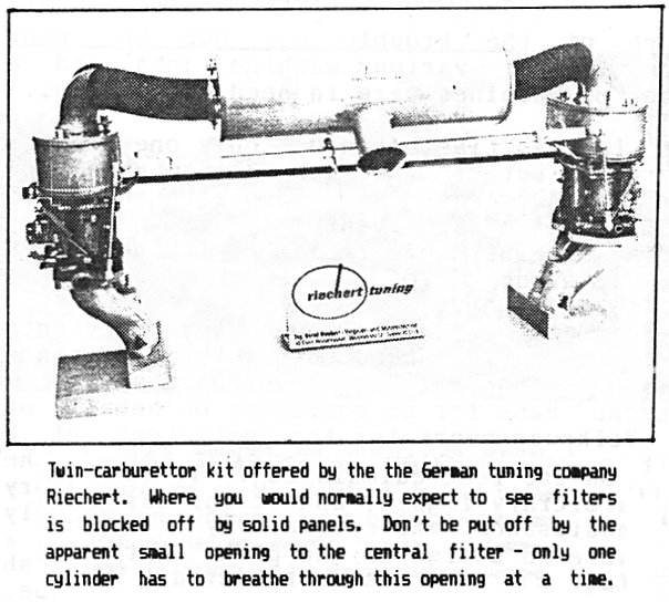
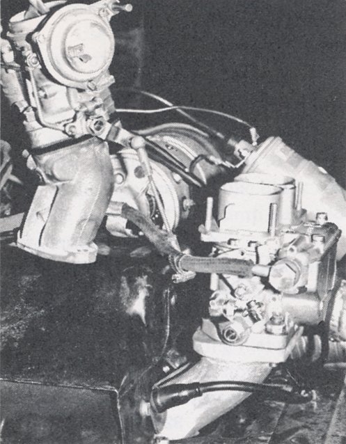
Fortunately, such a system for a Beetle can be built up. I'll give the credit for thinking of the idea first to some German tuning companies. Riechert made their own filter to fit onto a set of Solex PII-4s, and Oettinger used a stock late-model Beetle filter turned around for use with Solex 40 PDSITs. (Isn't it great when you can re-use the bits that you bought with the car instead of throwing them away?) Powertune Engineering also used to market a very neat cast aluminium filter housing for their Weber 46 IDAs. On my Beetle I have modified Oettinger's design and used a 1974 Beetle plastic filter housing. It was necessary to saw off the long intake snout and turn the housing end-to-end and around, so that the top then faced to the rear of the car. I cut off the upper part of the filter base, the bit that used to clamp onto the standard Solex, and riveted it to a new filter base that I folded up out of sheet steel and welded up. This new base sits next to the fan housing and has a circular fitting on each side onto which flexible hoses attach. These hoses in turn lead to the carburettor inlets. I have Weber DCNs and was very lucky in that mine came with some nice cast aluminium pieces that accept a piece of hose. If you don't have any such pieces, it is possible to modify existing individual filters to accept a hose fitting. Obviously the filter elements will have to be replaced with block-off panels to seal everything up. The details become clearer if you refer to the picture of the Riechert carburettor kit. The hardest part for me was making the sheet-metal base accurate enough so that it sealed well to the plastic parting face of the old filter. I ended up using some sealant in some of the cracks. I have had a Uni Filter foam element made up to keep flow restriction as low as possible, and to save on costly replacement filter elements.
There is an inevitable reduction in flow whenever extra plumbing is added to the inlet system. Just how much with this set-up I can't tell you, but the car seems no faster when the flexible hoses are off. What I can report, on the other hand, is that the noise is immensely reduced when they're on, more than you would believe possible.
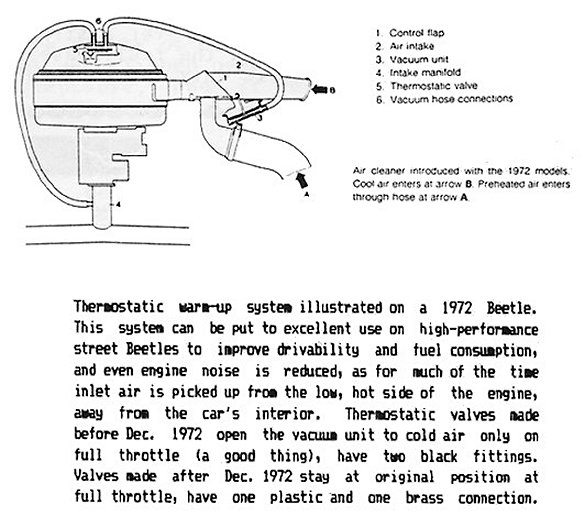
There is another great advantage to using Wolfsburg engineering. The stock VW filter comes with a vacuum diaphragm-actuated flap that mixes hot and cold air. The purpose of this system is something that is not well understood by many people, judging by the number of them I've seen disconnected. Ignorant people think, "It looks like an emission control gizmo so I'll rip it off", but the effects of this system are all good. A little thermo-vacuum valve in the filter housing feeds vacuum to the diaphragm at the filter entry, so that the temperature in the housing is maintained at a set level. When the engine is cold, hot air only is introduced, so a quick warm-up is achieved. As soon as the correct temperature threshold is reached, more and more cold air is bled in. Under full throttle, depending on the type of valve fitted (there are two different types), you get pure cold air, so that peak power is unaffected. The net result is that the carburettor under normal running conditions only has to cope with air at one temperature, so it can be more closely tuned to that temperature. You see, the hotter the air that an engine breathes, the thinner it is and the less oxygen it contains. Therefore less fuel should be metered to hot air. The carburettor can't sense any temperature difference (fuel injection can, by the way), so it's best to keep the inlet air temperature constant. The advantages in drivability when this system is maintained are most noticeable while the engine is still cold, and the engine idle quality is far less dependent on temperature. Fuel economy and emissions are both improved also. You should be taking advantage of this excellent engineering! Your Beetle deserves to have refined driving manners as well as a refined sound.
The icing on the cake is that the whole system looks as though the factory designed it that way. Undoubtedly the factory would have designed it that way if ever there had been an ultra-high-performance Beetle made in Wolfsburg!
Well-Balanced Carbs
By Rod Young
November 1988
It seems to me, after thinking about most of the worked VWs that I've had the occasion to drive or be chauffeured in, that the owners put up with a whole lot that owners of ‘normal’ cars certainly wouldn't, especially when it has to do with carburettor linkage and tuning.
If you compared the average ‘home’ installation with a factory set-up, you would see purpose-built castings and filter enclosures and custom-designed linkages, and if you looked deeper, you would find jetting and unique emulsion tubes developed after hundreds of hours of dyno testing at the factory. All this to satisfy the rigorous demands of performance, drivability, economy and emission control. The average backyard tuner, on the other hand, has no hope of matching this, and is usually concerned only with high performance, and to hell with the rest.
One of the most disconcerting features of all with owner-installed twin carburettors on VWs is a flat spot just off idle. This is usually a function of imprecise linkage, and there's nothing much you can do to synchronise the throttle openings exactly, given some of the linkages that are currently available from the States. I know that I used to spend at least every second weekend resetting the throttle linkage on my Beetle with twin Weber DCNs, because I just can't stand the lack of response and the vibrations that come through the driveline when the carbies are out of whack. And it doesn't take much for that to happen. On some linkage systems the synchronisation is even put out by engine expansion and contraction as it warms up.
It's easy to see how the lack of synchronisation takes place: while the engine is idling, all is fine, but as soon as the throttle cable pulls on the linkage, one side will always start to open before the other. Adjustment is only a matter of trying to reduce by how much this will occur. So there will always be a point at which one set of throttles is nearly closed, letting only the idle volume past, and the other set is cracked open, letting 2, 3, 4...? times the idle volume past, so that one side of the engine is receiving that many times more mixture than the other side, and it doesn't like it. As soon as the throttles are opened further, you don't notice any lack of balance, as the difference in airflow between them as a fraction of the total flow becomes less. That's why it's just that off-idle position where imbalance shows up.
Of course, there is something you can do about it, which is why I'm writing this article. Look again at the car with the factory installation and its absence of flat spots, and you'll see balance tubes between the four manifold runners. You won't ever see them on the after-market manifolds for VWs, of course, because they were designed for racing only. The balance tubes allow all four manifolds to "communicate" so that at low air-flow conditions, such as just off idle, each cylinder can breathe not only from its own carburettor barrel, but from the other three as well, thus balancing out any differences in air flow between the throttles.
This is something you, as the back-yard tuner, can do yourself, as long as the manifolds have enough "meat". Get four brass fittings from a hydraulic fitting store or elsewhere - 3/8-in BSP will do, as these are cheap and very available. Carefully drill through the manifolds, using a drill bit just larger than the valley of the thread on the fitting, and cut through with the right tap (you can borrow it from me). Then wrap thread tape around the fittings and screw them in tight, not too far, as these are tapered fittings and will eventually crack the casting if you keep winding them. Then put your carburettors and manifolds back onto the motor.
You can use 1/2-in automotive heater hose to connect the fittings together. It's best to use an equal length of hose from each manifold and join them all centrally; I made an X-shaped thing from two bits of 1/2-in copper tube. It sits above the fan housing and the four hoses run to it. Any vacuum tappings, eg. for a gauge, can come from here too.
There are some further adjustments to be carried out, as I found out. Because each cylinder can idle from four carburettors (it still gets most of its mixture from its own barrel), the idle speed will go way up, and the throttles will have to be closed further to compensate. This may or may not be beneficial for drivability (it allows more range for mixture to flow from the transfer ports). If you have a vacuum gauge, you will notice straight away that there is much more manifold vacuum available. Also, I can't guarantee that the jet tuning won't have to be changed, as I was in the middle of some tuning changes when all this took place.
The result? The basic throttle synchronisation setting is not nearly as critical as before, and I haven't had to adjust it once since I carried out the job. And no flat spots! Great!
Just an aside - if you had a combination of twin carburettors and power brakes in your VW - perhaps you have a 1600 Kombi - you would need to carry out this fix, as otherwise you wouldn't have enough vacuum for the servo to do its job properly.
Short Cables
By Rod Young
December 1988
This techno-fix involves the relatively minor problem of what to do when the throttle cable installed in your car is too long for the job because you've set up a different carburettor installation, and VW doesn't make one that short.
The solution I have encountered most often is where the screw is simply clamped down onto the cable instead of the small piece of steel rod that is now poking through the clamp. A very simple cure, but one which will lead to problems in the future, as the localised stress on the cable will lead to progressive breakage of the strands until the driver is left with no mechanical connection between the right and the left throttle lever. This can be embarrassing on Parramatta Road at 8:00 am.
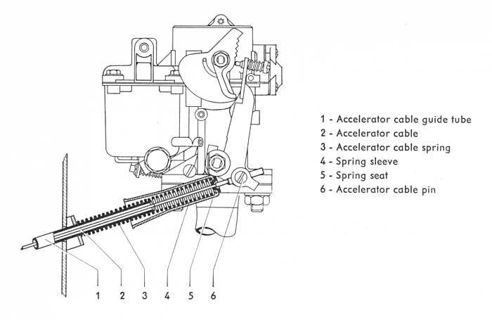
I suggest two simple fixes. The first involves cutting off the excess cable poking through the clamp and replacing the small piece, into which the strands of cable have been inserted and tightly crimped. I have successfully replaced this with a piece of copper tubing of roughly the same size as the original rod, crimped in a vice and soldered on the end where the wire pokes through for extra security. What does the trick very nicely is a windscreen washer nozzle from a Datsun 180B (and probably many other locally made cars). It has close enough to the right diameter and its bore is just right to accept the VW cable.
The second solution is for those loath to alter their VW parts in any way - it allows you to use your original cable without cutting. The idea is to fit a spacer made from metal tube between the clamp in the carburettor linkage and a new clamp that you attach to the rod on the end of the cable. The first clamp isn't actually clamping anything, but acting as a stop for the piece of tube, so the clamping screw isn't required. Just get a piece of metal tubing slightly larger than the piece of rod on the end of the cable, cut it exactly to length and slide it down until it hits the first clamp. Then fit another VW accelerator clamp to the end of the cable, cut it exactly to length and slide it down until it hits the first clamp. Then fit another VW accelerator clamp to the end of the cable hard against the piece of tube, screw it down, and the whole thing is locked together so that the excessively long cable does in fact open the throttle. The normal range of adjustment is available, as long as the piece of tube is cut to the right length. For a totally permanent job, the new piece of tubing can be brazed to the original clamp.
The Last Word On Float Bowls
By Rod Young
March 1990
I can attest from experience that certain carburettors, Weber 40DCNs in particular, suffer fuel surge on cornering, and I agree with the explanation that on horizontally opposed engines, ie. VWs, these carburettors are mounted sideways.
Just a bit of basic carburettor theory here. The vast majority of carburettors have offset float bowls, ie., the float bowl is to one side of the mixture discharge point in the venturi.
Imagine a U-tube with fluid in it. You have fuel on both sides at the same level. If you suck on one end, the fluid rises on that side of the tube. This is at the basis of all carburettors. When a vacuum, caused by airflow in the venturi, the point of restriction in the carburettor, acts on one side of a U-tube, the fuel level rises there and overflows. More airflow, more fuel overflow.
Now look at what else happens to a U-tube. If you accelerate it, ie. apply a force to it along the U, then the fluid levels change with fluid transferring to the rear. If it is accelerated across the U, then there is effectively no change to the fuel levels.
This same effect must also take place inside carburettors. A force on the U-tube causes the fluid, ie. fuel, to move to one side. Towards the discharge tube, and you get a richer mixture. Away from it and you get a leaner mixture. This can and does happen in the real world.
The correct orientation for carburettors with an offset float bowl is for the float bowl to be at the front and the venturi behind. Just look at any VW and you will find that this is the case. You can imagine the U-tube in line with front/rear axis of the car. A sideways force has minimal effect on mixture strength, but a front or rear force, due to acceleration or braking causes richening and leaning respectively. This phenomenon, though undesirable, isn't the end of the world, because richening upon acceleration is just what's needed and leaning on braking isn't such a bad thing either. The factory engineers take it all into account in the overall tuning picture.
But, if you turn the carburettor sideways, then cornering causes that same transfer in the U-tube, with inevitable richening or leaning of the mixture. In the case of a Beetle with 40DCNs, one side goes rich and the other lean during cornering. A Beetle with a centre-mounted two-barrel carburettor may cut out altogether during cornering.
The same can happen on Golfs which have had a Passat TS two-barrel carburettor and manifold bolted on. The Passat has a north-south motor and the Golf an east-west. The float-bowl orientation is different, so beware!
Now, you might notice that I have said that not all carburettors have an offset float bowl. Some, such as the Weber 48 IDA and sidedraft 40 DCOE, have a centre-mounted bowl. These are designed especially for racing, where typically greater cornering forces are encountered.
The central float bowl ensures that orientation of the carburettor isn't critical. The float bowl is in between the discharge tubes, so while the U-tube effect is there, it is minimised by the sides of the U being close together.
There is a design, though it is exceedingly rare, which virtually cancels out all mixture variation due to side forces. This is the concentric float bowl, and the only carburettor on which I have seen it was the Holley Buggy Spray (that's Buggy, not Bug). This carb was designed, as the name suggests, for off-road conditions, and had a float bowl which completely surrounded the barrels.
Picture now a double U-tube. Apply a force to it and the fluid levels change at either end, but in the middle the level stays as before. This is the effect which takes place in the Buggy Spray. The discharge tubes are roughly at the centre of the mass of fuel in the float bowl.
Now, I have two theoretical solutions for the problem of the Beetle with side-mounted DCNs. Theoretical, because I haven't had the time to try them.
First is to fit swinging jets. A special fitting would replace the original jets, to which a tube would be attached, on the other end of which would be the real jets. These would then be free to move around the float bowl with varying side force.
The other way would be to build in an extension of the float bowl on the opposite side of the carburettor, linked to the original float bowl by a tube of fairly large diameter so that fuel can flow quickly. The volume would be correct when, if the carb were tipped sideways, the level in the emulsion tube well would not change at all.
This second solution would be the easier to implement. I dreamt them up, but the reason why I haven't tried either of them is that I've since discovered fuel injection, which really does make carburettors obsolete.
A Whole Lot of Hot Air
By Rod Young
July 1990
I hope that my articles aren't always thought to be hot air, but that's the subject of this one.
Back in the early days of VW motors, a simple air filter sat on the carburettor, quite in keeping with the unsophisticated nature of the beast. This filter drew in cold engine compartment air and nothing more.
With the advent of the 34 PS (40 hp) motor in 1960, the air cleaner had a spout sticking out the left side and a small-diameter paper hose attached to the left heater box at the front. A weighted flap in the spout divided the air coming from these two sources, so that at idle and low engine air-flow, the engine received pre-heated air, then as the flow increased, it overcame the restriction of the flap and opened it to admit cold air. This was a simple and effective setup, and at the time, the benefits were described as improved warm-up, reduction of carburettor icing, improved drivability and improved fuel economy. All things definitely worth having.
This crude, but effective device underwent many changes, more than you would think decent, actually, until the final design was reached.
When the ‘fresh-air’ heater was introduced in 1962, the filter pre-heater hose was transferred to the rear of the engine, where it attached to the new heat exchanger. In 1966 a second small-diameter warm-air inlet was added and the filter gained a second spout. Finally, 1967, they went back to one large entry for the hot air on the right-hand side, along with a second flap to help evacuate the crankcase of blowby gases. None of these changes fundamentally altered the way the system worked; they were changes in detail only.
One of the minor disadvantages of the system as described is that it imposed a minor pressure drop on the entry to the carburettor, since the air flow had to overcome the weight of the flap. This translated to slightly less all-out power.
In 1969 the designers took advantage of the fact that the engine had a thermostat to actuate the mixing flap. A cable ran from the right-side fan-housing thermostat flap to the air cleaner. As this flap deflected, thanks to the thermostat, the air-filter flap also moved, allowing in heated air while the motor was cold and cold air when it was at operating temperature, at the same time not imposing a pressure drop on the inlet system.
The next redesign came in about 1970. Instead of making use of the existing engine thermostat, which possibly opened too early for adequate temperature control, a separate wax-pellet thermostat was incorporated in the filter housing. This little device is located on the front of the spout, where it's hard to see on the engine. It extended at a pre-determined temperature and its movement was transferred to the air mixer flap.
Then in 1971 they got serious about the reason for pre-heated air being there. It was about that time that emission control suddenly took on a very important meaning. The technical theory is that as inlet air temperature changes, so do the air/fuel ratio requirements. Air/fuel ratio fluctuations are undesirable from an emissions point of view, so two avenues are open: make the ratio react to inlet air temperature (this is how fuel injection does it, but it's difficult to achieve with carburettors) or stabilise the inlet temperature so that the carburettor can be tuned closely for one particular temperature. Virtually all recent emission-controlled engines have a thermostatically controlled air filter inlet for just this purpose.
So, there was another design of the air filter. The mixing flap was actuated by a diaphragm, which in turn gets its motive force from low-pressure air, otherwise known as ‘vacuum’, from the inlet manifold. The amount of vacuum is regulated by a thermostatic valve which sits in the filter where it can react to inlet air temperature. This valve is very clever: it bleeds in a tiny amount of atmospheric air to the diaphragm, so that its position can vary. It's a closed-loop operation: if the temperature rises, more air is bled in by the valve and the flap opens to admit more cold air. The temperature now drops and the valve reacts by admitting less air to the diaphragm, which closes slightly and allows more warm air in. And so on, ad infinitum, but in a very smooth and controlled fashion.
In 1972 an important change was made, but one which is hardly visible. The thermostatic valve was previously of the type which reverted to completely cold air under high engine load. High load meant no vacuum, and no vacuum meant nothing to hold the flap shut to cold air. They changed the valve for one which did hold the flap in its original position. It's identifiable by having one plastic and one brass connection. On previous valves, both connections were plastic.
Finally, 1973, the plastic air cleaner with the paper insert came out. This filter had the same type of pre-heated air mixer as already described, and we've had that ever since. They finally got it right!
If you're making modifications to your motor, this is a system you can definitely do with, for the reasons mentioned in the third paragraph. For slightly more power, use the 1971-1972 thermostatic valve, as it opens to cold air when you accelerate.
If you have twin carburettors, however, there is a dilemma. Usually very little manifold vacuum is generated with such set-ups, and at anything more than light cruising conditions there is insufficient vacuum to hold the flap closed. You either have to use the late-model type, which does hold the flap closed, as I have done for many years, or resort to what I recently did.
I don't mind doing this sort of job, as I like such tinkering. I installed a full-throttle microswitch and a three-way vacuum solenoid which dumps atmospheric air into the diaphragm when you mash the throttle. So when you want maximum power, you get all cold air. I might be kidding myself, but I think I can feel the difference.
Other VWs have had a range of filters fitted to them, as with the Beetle. Early Type 3s had a manually operated flap which you flicked over, depending on the season. Very crude, and a system retained by many Japanese cars until recently. They then adopted the wax-pellet type, but never installed the diaphragm.
Early Golfs with the remote filter had a wax pellet thermostat too. Later types with the carburettor-mounted filter had the diaphragm. For many years now, anything with a VW badge and a carburettor in it has the diaphragm type of mixer flap. You could hardly improve on it.
Racing Fuel Basics
By Ronald Hansen
December 1992
In its broadest meaning, ‘fuel’ means a substance that can be combined with oxygen for combustion, or otherwise burned. The heat produced is then converted into useful work, and during this process losses will inevitably take place. It is the function of the engineer to keep these losses at a respectable minimum, although it is axiomatic that this ‘acceptable minimum’ is a function of the specific job we are asking our engine to perform. The designer of a utility engine has, as a foremost consideration, utility; that is, economy, or getting ‘the mostest from the leastest’. A racing car engineer is not worried about fuel consumption so much as maximum power per unit displacement.
In this article we’ll consider racing and hotted-up street engines and their requirements. These engines use only liquid fuels, because they are the most convenient. And of all the combustible substances known, only a handful are employed, in mixes ranging from pure petrol to highly complicated - and sometimes secret - brews concocted from half-a-dozen substances.
The internal combustion car engine may be supercharged or normally aspirated, the former system allowing large quantities of air/fuel mixture to be pushed into the cylinder every time the intake valve opens, while the unblown engine receives no boost and has to depend on its ‘sucking’ powers for its mix. Thus the theoretical maximum between volume of mix drawn in and cylinder volume (this ratio is called volumetric efficiency) is 100%. In practice this is rarely achieved, except in some race motors with specially designed intake systems, where use is made of the ram action of the resonance waves in the air to attain 100% filling (in one instance 102% has been reliably quoted due to inertia of the entering column of air). However, ‘induction ramming’ is a complicated stunt and is outside the scope of this article. And in any case, it only works at one particular RPM, not over the engine range.
The more mix you get into the cylinder the higher the pressure which results when it is fired, which means that power and torque are boosted accordingly, both being directly related to combustion pressure. But the mixture must always be in the proper ratio; that is, there must be enough air to ensure a chemical reaction between oxygen and the carbon and hydrogen in the fuel. In practice, this ratio is kept a little on the rich side so as to stop the excess air from burning (oxidising) the piston and plug electrodes.
Any carburettor built and adjusted for a certain fuel - usually petrol - must be readjusted when a different fuel is to be used. This means the float level (to compensate for different densities) and the fuel/air ratio, which is different for every type of combustible mix. For instance, if your carburettors are set for a fuel density of 0.730, which is correct for normal petrol, and you wish to use methanol (0.796) with 20% benzol (0.884), the following calculation must be done to obtain the overall density of the new mix: (0.796 x 0.8) + (0.884 x 0.2) = 0.816.
The difference in this case is more than 10% (11.8% actually), quite enough to upset normal functioning of your petrol-tuned carbs. The float level must be adjusted so that the needle will close with the float 11.8% closer to the top of the chamber than before.
Most important, however, is the jetting correction for the new fuel. To avoid the use of complicated chemical formulas to find out the amount of oxygen required to burn a given fuel, tables have been created giving the amount of air in kilograms necessary to burn one kilogram of fuel. Fuel companies can supply these tables on request.
Thus, we learn that 1 kg of petrol burns best with 15 kg of air, but methanol burns best at 6.43 kg and benzol at 13.2 kg, so when you switch fuels a lot of jet corrections are necessary.
So for our example, (6.43 x 0.8) + (13.2 x 0.2) = 7.8 kg of air per kg of fuel. Since our jets are currently set for the normal 15:1 ratio, new jets must be fitted to give the required 7.8:1 mix. The orifices should be enlarged by a factor of 15/7.8 - that is, 1.9 times bigger.
If further ingredients are added to your custom fuel mixture, they must also be incorporated into the calculations, unless their amount is very small or their physical properties are very similar to other components already allowed for. The final adjustments must be made with the car on the road or, ideally, a dynamometer.
But why do we want to make these changes? What we know is that we need more power from an existing engine. We can't make substantial changes in design, but what we can do is tune it so the power it develops is increased.
The first DON'T for any fuel is DON'T induce ‘knock’, either from pre-ignition from a hot spot in the combustion chamber, or the phenomenon of ‘pinking’, which seems to be caused by a mix burning so quickly that it pushes a shock wave to the far corners of the combustion chamber, and this shock wave compresses the mix in those far corners and sets up a secondary combustion. Design of the combustion chamber has a lot to do with prevention of knocking, but when your compression ratio goes above about 10:1 not even the very best straight petrol, even the mix known as ‘100-130 octane’, can prevent detonation. And in any case, few stock engines have optimum combustion chambers anyway.
About this ‘octane’ business. Octane is a measure used to scale detonation resistance in a standardised test engine with varying mixtures of heptane (zero octane value) and iso-octane (100 octane value). The amount of iso-octane needed to just prevent detonation at every different compression ratio value (the test engine has an adjustable C.R.) determines the ‘octane rating’, and the octane rating of any fuel is determined by ascertaining the maximum C.R. it will stand without knocking and comparing it on the iso-octane/heptane scale. Thus, if a fuel just avoids knock at the same C.R. at which 82% iso-octane (and 18% heptane) does the same, then its octane rating is 82. In principle it should therefore be impossible to get over 100 octane, but certain substances have the property of allowing compression ratios higher than pure iso-octane, under special conditions of combustion.
In any case a new standard is now being used, which also takes into account the burning speed of the fuel. This is of the utmost importance in a racing engine, where the time allowed for combustion is extremely short, and the fuel must be completely burned before the piston reaches bottom dead centre. It is for this reason that aviation petrol is NOT suitable for a high performance auto engine. Although AVGAS does have a high octane rating (it resists knocking extremely well), it burns too slowly. A normal Lycoming or Continental aeroplane engine is red-lining at 2500 rpm.
On the other hand, methanol and ethanol (alcohols) are recommended because they burn very quickly and have high octane ratings, but also because of their very high latent heat value. This is a measure of the extent to which a fuel absorbs heat when it evaporates (thus cooling its surroundings). A high latent heat value is of great importance in a racing fuel, because as air cools it contracts, and thus a greater amount per volume can reach the combustion chamber. The more air, the more fuel is swept in with it. Methanol alone can give you a 10 to 15% increase in power, and this increase can be even greater if advantage is taken of the possibility of increasing the compression ratio.
Sometimes race regulations ban alcohol, and sometimes its high price and its high consumption penalty prevent tuners from using it. If you do use alcohol, it is advisable to add small quantities of benzole and ether for easier starting, which can be difficult on straight alky which is very cool. However, ether has a low octane rating and both have low latent heat values and must be used sparingly.
Acetone is not a good fuel in itself, but has very good anti-knock properties and is especially useful in fighting pre-ignition (by incandescent spots in the combustion chamber). Pre-ignition rarely happens in race engines, but is common in hotted up street engines with increased compression ratios but still using straight petrol. In these cases, adding up to 10% acetone to your petrol can usually eliminate the harmful effects of pre-ignition. The relative density of acetone is 0.796 and the amount small, so carburettor adjustment will not be needed.
It is important to remember that the ‘improvements’ in gasoline are obtained mainly by refining it as much as possible, but when the possibilities of straight refining have run their course, small quantities of tetraethyl lead (TEL) are added. However, as is fairly well known, TEL has a tendency to break away from the compound during combustion and deposit itself on the engine's vital parts, and though this is not a problem in a stock engine it becomes troublesome when a racing engine is being used. Therefore it is advisable to use unleaded petrol of no more than 90 octane and bring it up to 100 by adding benzole.
Modern sports engines are designed for trouble-free running on 95. However, older sports and standard engines can advantageously use a third/third/third mixture of petrol, benzole and ethyl alcohol. Supercharged engines work best with a methanol mix, because the high latent heat of methanol helps to cool the fuel/air before it enters the cylinder, and also to cool cylinder walls and cylinder head, which always have a hot and sticky job in blown engines which develop far more power per unit displacement.
Past experiences with blown Grand Prix cars indicate that the best fuels are those with a high (70-80%) methanol content, plus 10 to 20% benzole, a little ether and acetone (5% between both), and a little caster oil to lubricate the supercharger's moving parts. In their pre-war Grand Prix Auto Unions and Mercedes, the Germans used a proportion of nitrobenzole, which is an oily fuel, and not only lubricated the superchargers and the intake valve stems, but was later completely burned up in the cylinder, actually raising the power and smoothing combustion.
Nitrobenzole takes us, of course, into the field of nitrated or oxygen-bearing compounds, widely used today to increase powers to limits far beyond what was ever thought possible for unsupercharged engines.
The power an engine can develop is directly related to the amount of correct fuel-air mix that can be drawn in at each intake cycle. Thus a two-litre engine cannot draw in more than 2000cc of fuel-air for every two crank turns. Even this is hardly possible, because normally an 80% volumetric efficiency is the best that can be obtained. The point is that for efficient burning you can't beat the 15:1 air-fuel mix, and as you can only draw in so much air per cycle, you can only burn so much fuel, and that's that.
However, nitro compounds have two atoms of oxygen in each molecule, and when combustion occurs this extra oxygen is liberated and can be used to burn more fuel. In other words, the fuel takes its own oxygen into the combustion chamber and lets it go at the moment of combustion. So if we use a common fuel, plus a nitro compound, we can lower the intake fuel/air ratio because we'll be getting more oxygen inside. Thus more fuel can be satisfactorily burned and more power churned out at the flywheel. The use of nitro compounds is limited only by the physical ability of the engine to stand the greatly increased power (apart from the fabulous cost).
After many experiments it has been found that of the nitro compounds used (nitrobenzole, nitropropane, nitromethane), nitromethane is the best due to its physical properties and to the high amount of oxygen it liberates. In top fuel dragsters and Indianapolis classification trials, up to 50% of nitromethane has been used, but a more conservative mix would be 15% nitromethane and 85% methanol - this latter is a must to keep the engine cool.
All these oxygen-bearing juices, and their mixtures, are explosive and should be handled with great care. Furthermore they are poisonous and their vapours are highly noxious, so their use is a very tricky business. But for the serious ‘to the limit’ tuner, the results are well worthwhile. The DOs in this case are: clean containers; never allow the liquid to touch the skin; avoid spillage; no sparks near the containers; and always work in the open.
Generally speaking all fuels must be carefully handled, even though they may be less devastating than nitros. Containers should always be clean to avoid contamination, and filtering should be resorted to wherever possible. The author once had the experience of a magnesium alloy crankcase starting a chemical reaction with the methanol-based fuel used, but as too many variables were involved it proved impossible to determine why it happened. Maybe it'll happen to you. But in racing anything can and does happen, so one more incident doesn't make any difference.
Fuel Injection & Engine Management
By Phill Lander
April 1993
In 1967 (1968 model year), the Volkswagen Type 3 Fastback became the world’s first mass produced car with electronic fuel injection. Since then most manufacturers have switched to fuel injection, as they have found that it is much more reliable than the modern complex low-emission carburettors, with easier starting, better fuel economy, more power and smoother running.
Volkswagen fuel injection systems can be divided into two groups, ‘Pulsed (Electronic) Systems’, which are sometimes referred to as ‘Electronic Fuel Injection’ or EFI, and ‘Continuous Injection Systems’, or CIS, which is now mainly used on Audis. Electronic fuel injection regulates the fuel flow by adjusting the dwell or turn on period of the injectors electrically. Continuous injection systems regulate the fuel flow by adjusting the fuel pressure to the injectors.
ELECTRONIC FUEL INJECTION (EFI)
D-Jetronic
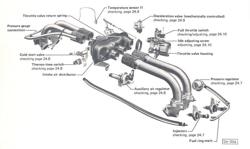
This was the first Bosch Jetronic system. The ‘D’ stands for Druck, the German word for pressure. Manifold pressure is used to indicate the engine load or how much air the engine is using. This pressure is the input signal to the control unit (ECU) for calculation of the correct amount of fuel delivery. This system was the forerunner of the now widely used L-Jetronic, which uses an air flow meter for sensing. The injection pulses are synchronized by trigger contacts built into the ignition distributor below the mechanical advance mechanism, which operates the injectors in pairs. D-Jetronic was mainly used on the Type 3 and Type 4.
L-Jetronic
The ‘L’ stands for Luft, the German word for air, since it measures the airflow by an airflow sensor with a movable vane to indicate engine load. The deflection in the airflow sensor is then converted to an electrical signal by a potentiometer (similar to a fuel gauge sender), and fed to the electronic control unit. This is then compared with engine rpm and signals from other sensors such as engine temperature, throttle opening etc, which causes a variation in injector pulse duration. This system was mainly used from 1974 to 1984 on Type 4, Type 2 and Beetles.
Digijet
This is a Volkswagen version of Bosch L-Jetronic. This system was used on 1985 Type 2 water-cooled engines.
Digifant
Another of Volkswagens own development, this is based on the Bosch Motronic engine management system. This differs from the previous EFI systems as it controls the ignition timing as well as the injector timing. The ignition advance is controlled by a pre-programmed ‘map’ instead of the mechanical and vacuum system used previously, which was prone to wear. This system uses the Lambda Closed Loop Control system for fine adjustments to the fuel mixture.
The Lambda sensor is mounted in the exhaust pipe and used in conjunction with the catalytic converter for the most effective method of controlling exhaust emissions. The method of operation is based on the principle of a galvanic oxygen concentration cell with solid-state electrolyte (like a battery). The solid-state electrolyte consists of a gas-tight ceramic body closed at one end. It is made of zirconium dioxide and stabilized with yttrium oxide. The surfaces have electrodes on both sides made of a thin gas-permeable platinum layer. The platinum electrode on the outside acts as a small catalytic converter; ie. the exhaust is subjected to catalytic aftertreatment and brought into stoichiometric equilibrium. On the side exposed to the exhaust gas, there is a porous ceramic layer that serves as a protection against contamination. The inside open space is in contact with the exterior air as a reference gas. The ceramic material used in the sensor becomes conductive for oxygen at 300°C.
If the oxygen concentration differs on the two sides of the sensor, a small voltage is produced. This voltage is then read by the ECU, and fine adjustments are made to the injector timing automatically.
Digifant II
This is a more refined version of Digifant with control improvements. It also uses a knock sensor for more precise ignition timing control.
The knock sensor detects solid-borne vibrations from the engine block and converts this to an electrical signal, which is fed to the ECU. Once knocking has been detected, the ECU retards the ignition point for the appropriate cylinder by approximately 1.5°. This process continues until the sensor no longer detects any knocking.
Digifant and Digifant II is used on most 8V Golfs, Jettas, Passats and Transporters since 1986.
Motronic
Bosch Motronic is a complete engine management system combining fuel and ignition control, similar to Digifant II, and includes a self diagnosis function. This system is fitted to the Golf, Vento, Passat and Corrado VR6.
Mono-Motronic
This is a budget engine management system designed to replace the carburettor on the more basic engines, yet still have low emissions, good fuel economy and smooth running. This system uses a single injector centrally mounted on a carburettor-style manifold. Mono-Motronic is used on the smaller engines (1.4 and 1.8 litre) of the Golf 3 and Vento.
CONTINUOUS INJECTION SYSTEMS
K-Jetronic
Volkswagen first used this simple efficient and reliable system on the Golf GTI. Bosch called this system ‘K’ for Kontinuerlich, the German word for continuous. A circular plate in the airflow sensor measures airflow. Fuel delivery is under mechanical control, with no electronics on this system.
The airflow sensor, the mixture control unit and the fuel distributor are housed in the one unit. As the airflow increases, the circular plate of the airflow sensor is moved upwards, which lifts the control plunger of the mixture control unit. This increases the fuel flow to the fuel distributor, which increases the amount of fuel injected.
Used on most types of Volkswagen and Audi in-line motors since 1976.
KE-Jetronic
Similar to K-Jetronic with an electro-hydraulic pressure actuator included in the fuel distributor. This electrically controls the fuel pressure to the fuel distributor, so that the air fuel ratio can be automatically adjusted for engine temperature, engine RPM and throttle position. A lambda sensor can also control the KE-Jetronic system, in a similar way to the electronic pulsed injection systems.
KE-Jetronic is fitted to most types of Volkswagen and Audi in-line engines both 8V and 16V.
KE3-Jetronic
This is KE type fuel injection with the control of ignition timing. The fuel injection and ignition control are in two separate units.
This system is used on some Audis from 1987, and is sometimes referred to by Audi as CIS-E 111.
KE-Motronic
This is a KE type system with full engine management control of fuel and ignition timing, including knock sensing within the one control unit.
Used on 16v engines in Golfs, Passats, Jettas, Sciroccos and Corrados.
POWERCHIP - Fact or Fiction?
A lot of people think this is an easy way to gain horsepower from electronic fuel injection systems. As with most engines, there is no cheap and easy way to get any significant horsepower gains.
The word ‘Powerchip’ is derived from the German word for ‘Wallet Emptier’. Just imagine that you gave me $300 and in return I gave you a non rev-limiting rotor, drilled out the main jet of your 34 PICT carburettor, and re-curved your distributor. Would you be happy? How much horsepower do you think that you would gain?
With the newer knock-sensor ignition systems there would be little to gain from changing the ignition map anyway as the electronic control unit constantly updates its advance curve to suit optimum power and efficiency.
There is little to be gained from increasing the amount of fuel to the engine as at full throttle the engine is tuned for power and not emissions anyway. The ‘L’ type air flow sensor is fully open between 3,500 and 4,000 rpm, so increasing the amount of air into the engine can cause it to run lean at higher rpm. Even if you could get the ECU to increase pulse time to deliver more fuel to your engine, time is another factor that will limit high rpm fuel delivery. The amount of time with which the injector has to open and close within the pulse period gets smaller as the rpm increases until at peak rpm the injectors are open nearly all the time. Even if the ECU could be reprogrammed for increased pulse time and more fuel delivery, there may simply be no more time available.
Haltech Programmable Fuel Injection
By Jeff Unwin
July 1994
All the way along, speedway racers have used mechanically run fuel injection (PI) pumps (the pump was actually belt driven off the front pulley) which then pressure fed alcohol to the injectors. The mixture settings were a 'black art', changed by the fitting of larger or smaller pills. This system worked really well compared to carburettors for methanol guzzling flat-out racing type applications, but was as subtle as a fart in a lift when it came to daily driver applications.
Volkswagen has used (on some models more successfully than others) varying Bosch fuel injection systems.
The early TLE T3 Volkswagens and ‘76 to ‘83 two litre air cooleds ran the Bosch D Jetronic (D for ‘druck’ – pressure) and L Jetronic (L for ‘luft’ – air) respectively. The injectors tended to wear relatively quickly and the system began running lean, causing overheating, premature engine wear and burnt valves. I would probably estimate that more than half of the models fitted with this model FI would have been converted to carbies by now.
The 1.9 and 2.1 Waterboxers ran Digijet and Digifant systems respectively; GTI Golfs—L Jetronic; VR6 Golfs— Motronic; while Audis varied from KE Jetronic to L Jetronic systems.
As can be seen there were many and varied systems manufactured mainly by Bosch. They did have adjustable mixture trims but could not be drastically 'retuned' to take into account much larger capacities, long duration cams etc, and that means all the nice hot up work that we VW loonies do to our motors to get them to perform and go!
The PFI system that I am writing about here is the Haltech F3 Programmable Fuel Injection (HPFI). This system uses a very sophisticated programme that is accessed through any IBM compatible 386 or 486 laptop computer.
Don't think for a moment it is a job that you can do with a few mates on Saturday arvo with a case of beer and a few tools. It definitely is not, but by the same token if you take you time, plan it out and get some correct advice from someone who has fitted one, the job is not very daunting. This is especially so now that PPI has been around for about six or so years and all the ancillary parts are pretty well available off the shelf or can be sourced second hand from a wrecker of late model cars.
The great advantage of PPI is the varying applications that it can be matched to, such as: Multiple throttle body direct port injection, single throttle body direct port injection, single throttle body single injector injection, single throttle body direct port turbo intercooled, multiple throttle body direct port supercharged, single throttle body direct port staged (second set of injectors phased in at say 1.0 bar boost ), turbo intercooled, single or multiple throttle body direct port, staged injector supercharged. The last two can be set up so that the second set of injectors can be programmed to come on at any rev point or pre-determined boost pressure.
Add to this the newer systems which allow for total engine management i.e.; timing function as well, you could very easily get that retard on your dizzy when the boost comes in, to stop all that pinging and detonation on a boosted engine system. Basically they can do any configuration engine! Full stop!
Once upon a time there were two VW psychopaths. In 1988 Jo Smith and I were racing the ‘Bug out of Hell’ racecar in the NSW Hill Climb Championship, under the Rogwin Motorsport banner. As the racing fever got hotter and hotter we kept upping the ante to try and catch the three-litre Porsche of David Withers. Eternal optimism had us entered in the 2-3 litre Road Registered Class in a 1904cc 'dub (90.5 x 74 mm). (Funny, the 2161 cc (84 x 90.5) motor never did eventuate that year). We started off with 45 Dellortos and standard valve ported Berg heads, and ended up with a set of 48 IDAs (a friend had bought them back from the ‘States and Henry Spicak had set them up for us), and a set of Mark Walker 40 x 37.5 ported heads. The passion for speed was still there as David ended up taking out the championship by seven points; Jo and I finishing third and second respectively. We must have made an impact coz' Porsches were no longer allowed to run the Road Registered class; only as Marque Sports Cars for 1989.
It was during the later half of ‘88 that a friend of a friend (Wayne Glasser) had started taking a fair bit of interest in our racing activities and was calling around a couple of days a week hassling us to try one of the new Haltech systems. I cannot remember what I had sold but the money from its sale went into the purchase of Haltech F3 unit number 25.This was early days for PFI and I hadn't yet come to grips with computers so the unit just sat there for a couple of months.
Besides 1988 being our Bicentenary Year it was also a pretty big year for us with all the racing and the prospect of strutting our stuff in the hot-mix lap dash battle at Valla Park in August. As it turned out, Jo and I always headed up to Valla early so we could have a bit of a rest before the VW invasion took place.
Donna Pell had told us that we would have to meet Gene and Dee Berg at Nambucca Railway Station. We were the two free souls up here who had nothing else better to do. For the previous years all we had heard was "Berg this, Berg that" from Richard, so we joked about being like Moses and having to go to the station and receive the Ten VW Commandments (For those of you who don't know Richard, he has the ability to talk a Tom Thumb bunger up to a Hiroshima H bomb blast. There's no disrespect there Richard but you had us feeling pretty awed out.)
We picked up Gene and Dee and had a great night playing carpet bowls in at the Valla Resort and talking big motors. We talked more after the practice session on the Friday and had soon ordered a set of 44 x 37.5 heads, 84 mm wedge-mated crank and flywheel, Carrillos etc. Over the weekend I had told Gene about this new high tech HPFI system that we had bought. He was excited about the concept and agreed that if it did do what was claimed it would be a world first - he couldn't come to grips with the programme that would be needed to analyse all the different inputs from the sensors and then trigger the injectors.
As it turned out Gene had been playing around with both turbos and supercharging and mechanical fuel injection, with the same old problem - lean out at elevated boost pressures. And, yes he did have a couple of what he termed 'crude throttle bodies' that would fit onto a 48 IDA manifold. Gene had always talked about his pile of discarded VW parts that hadn't come up to required standard; well it wasn't until I was over there two years later that I got to look at the pile - he must have just about tested every VW hot up part that was ever made, as well as the prototypes of his own that were never made! "Yeah, sure,” Gene said, “you can have them.” The first parts on the shopping list found. You bloody beauty! Our friend Wayne Glasser took the Scat track inlet manifolds and managed to graft on a patch of alloy with his TIG, so we had a platform on which to mount a set of Camira fuel injector holders. We put the whole set up in the mill, bored a hole and there was our first set of direct port injection manifolds. Now it was time to fit up the injectors. “Well, what size are we going to use?” we asked.
“How much power are you going to make?” asked Wayne. “Well, the old 1904 with 40/37.5 heads, K8 cam, 45 dual Dells and 1 5/8” merged exhaust put out 98.5 kW on the Maztech dyno,” I replied. “So I think this 2161 with 50mm throttle bodies, FK87 cam, 1 ¾” race merged exhaust and so on would have to run at least 150 kW.”
The calculations were done and a set of Bosch 0280 1500 34-060 injectors were fitted up to the now modified manifolds.
Due to the non-availability of such simple parts as fuel injector rails we had to put on the thinking caps to come up with simple solutions. The fuel rails were made using brass 'T' pieces inter connected with small lengths of FI hose from Tooleys. Not the prettiest fuel rail but it sure worked. The list went on, a real Hitchhikers Guide to the Retrofitting of PFI onto a VW Bug.
The throttle bodies that Gene had sent were void of any velocity stack or ram tube so they too had to be made.
It was now time to fit the whole lot up on the motor in the car. The fuel rails stuck out as far as a stallion would approaching a mare. So we pulled everything out after marking out the areas to be cut. A combination of jigsaw and die grinder seemed to work best and after three attempts and three hours everything seemed to fall into place. The only other problem was that so much dirt and rocks could get into the engine compartment so we had to devise a seal to go over the rail. Six self tappers and a hunk of inner tube were all that were needed. A phone call to Finer Filters had the air filter made up and dispatched in two days.
Now that all the engine compartment manifolding and rails were in place it was time to run the tank fuel line from the tank to the pressure regulator and return line. We opted to run the fuel injection hose tie strapped to the outer pan rails down each side. The fuel pump and filter were mounted on the front of the pan opposite the master cylinder. A larger fuel tank outlet (7mm) was made from a barbed fitting to match up with the FI hose. The return line was routed so it dumped into the petrol tank filler neck - only two late nights for this one!
We had been advised by the powers that be (Mark Boxsell from EFI Technologies) to fit a fuel pressure gauge to help with the initial Haltech set up, so a 0-500 kPa VDO gauge was purchased and fitted on the interior of the rear firewall.
Next was the CPU (Central Processing Unit) which was mounted on a one millimetre thick aluminium sheet, acting as the driver’s side rear trim. Rubber mountings were used to isolate the CPU from our race suspension. A mini electrical board was also fitted, with fuses and push on terminals, to facilitate the set up.
The fuel pump relays and associated wiring were run and hey presto! The only thing remaining was to run the loom through the firewall into the engine bay and connect the various sensors.
Who were we trying to kid? Still more to do.
As the Haltech CPU was set up for MAP (manifold absolute pressure) as opposed to throttle position we drilled and tapped each inlet manifold runner about 50 mm under the butterfly shaft and fitted up four brass fittings that would take ordinary braided vacuum line. These hoses were then connected up to a fabricated metal vacuum box that would average out the vacuum pulses so a static single vacuum signal could be fed into the MAP input of the CPU.
The mixture trims wiring was temporarily run from the CPU along the centre main loop of the roll bar using tie straps. This trim would then be used to do the initial set up of the fuel curves. When I say initial, the big plan was to fit in a Celica fuel curve, do the start up tuning by ear running through the rev ranges in neutral, 'til we had a clean running engine that was at least able to drive out of the workshop and onto the road. Once on the road with an oxygen sensor enema we could then actually get the motor tuned using the mobile exhaust gas analyser (EGA) in conjunction with the + or -10% mixture trim and laptop computer. At a later date a dyno session was to be organised to maximise the fuel curves for performance and power.
Even though we were totally and utterly stuffed by this time adrenaline soon overtook tiredness as the motor fired up first go (after getting the initial fuel pressure by turning the ignition key on and off, and listening to the fuel pump purging all the air from the system). To start off with you couldn't really rev the motor as there were load points at which the mixture was wrong. It may have been correct for the Celica but not this 2161 boxer with balls. It was crying out for more fuel! With Wayne Glasser and Mark Boxsell hovering over the EGA and laptop it was hard for us two mortals to get even a look in as to what was being fiddled with.
Time out for the two Js while the two EFI crazies waved their magic mixture trim over the CPU. Sitting outside the workshop we were numbed by the feeling of accomplishment, that yes, this had been the first HPFI fitted to a VW. Our ears were ringing to the sound of the 1 7/8” merged with a Supertrapp, the whine of the straight gears and our noses were blessed with the aroma of BP100 wafting out from within the bowels of the Rogwin workshop.
Before we actually had time to get the caffeine buzz Wayne and Mark had gone through the revs up to 6000 so there were no apparent ‘no load’ dead spots; only the raw bark of a boxer on heat! It had only taken 15 minutes. It was now time for the first test flight.
The oxygen sensor wiring was taped to the bumper, whale tail, roof gutter and then into the cabin. Mark adjusted the seat belt tightly (perhaps he knew how fast we were actually going to be going or maybe had seen through my hell-bent eyes).
The same process as before was going to be used go though the various rev ranges in 1000 rpm intervals, get all the load points correct using the mixture trim to change the mixture which was monitored on the EGA. Piece of piss. The only major problem encountered was that it was completely useless using the first two gears as they disappeared into the next before you had time to make any adjustments! Third was chosen as it gave us a little more time. As the load points were tuned the mixture trim came into its own - the motor would be lead at say 4000 revs - mixture trim 10% richer – wambo, the car took off like I just hit a nitrous button!
Half an hour later the really fine tuning was in progress, third gear disappearing as quick as the full feeling after a Chinese meal. Top gear! More hassles here, we were starting to go too bloody fast. Poor Mark was stuffed into a standard 1500 low-back seat, had to juggle the EGA on his left knee, the laptop on the other to adjust the mixture trim and hit the update button on the laptop with Jeff ‘Rocketman Onion’ Unwin driving from 2000 to 7500 rpm in top gear around the back streets of Taren Point. I think Mark must have had a set of ‘tear off’ undies that night, coz the stress was starting to show!
By the time 50 minutes had elapsed, we were adjusting the accelerator pump functions of the Haltech; i.e.: length of time of injection and decay of pump stroke. In five minutes there were no more flat spots. As it turned out, we never did get to put that motor on the dyno. We ran the 2161 for about four months but had heaps of trouble with oil surge - the jump from Road Registered Class type tyres to Sports Sedan slicks, stiffer suspension, sway bars and much, much more power soon turned into a total nightmare. This motor suffered a terminal blow up while representing NSW at the Morwell Interstate Hillclimb Challenge, kicking two Carrillos out the top of an ARPM case, creating a five piece camshaft, destroying two pistons and liners and digging a three mil' gouge into the crank!
I can joke now but all was not lost as the pieces ended up becoming the dreaded ‘Bent Carrillo Trophy’, the most feared award at the annual Hillclimb presentation night. If you ‘win’ this one, you've had the best engine blow, bar none, for the year.
In-between all this trauma we did have some success which the history books proudly show but space limitations here prevent us from reporting.
Over the preceding page I have referred to ‘load points’, so an explanation is needed. If you look at a carby, it has basically three load points i.e.; idle speed and mixture, progression circuitry for transition from pilot to main circuit and the main circuit itself. The 48-IDA is a very easy carb to tune but does not exhibit much smoothness as it has no progression; basically it should be used for idling in the pits or flat out racing around; not for driving on the street for which it was never designed. The greater the number of load points the better or smoother the engine will run. What we found was that the HPFI filled in the gap under which the cam kicked in, by virtue of its 512 load points. It's like a virtual reality thing - being sucked into feeling that the motor isn't going that hard whereas it has so much more bottom end that the cam step doesn't appear to be that big at all.
I'll never forget going out to Kurnell in the wet one night with the Bug Out of Hell having 185/70-14 tyres on and being able to squeeze the throttle at 80 km/h in top gear and having both tyres light up and keep spinning through to an indicated 120 km/h. That’s drivability at a rev range that would bog down with carbs and a similar camshaft.
In conclusion there is no doubt PFI is here. This is 1994 and we are heading towards 2000, so if you want to upgrade and update your ride so it is as smooth as all the other 1994 FI cars give Haltech PFI a really big sussout before purchasing a bigger set of carbs.
Mixture Screw Blues
By Lance Plahn
January 1997
At this point in time, most carburettor mixture screws have succumbed to the problem of seizing in the carb body. Carburettors most likely to be affected are 34 PICT-3 and 34PICT-5.
The occurrence of this problem could be reduced by removing and cleaning the threads of the mixture screw, then lightly coating the screw with some of your favourite lubricant or anti-seize product. At the same time, it is advisable to lubricate the choke-shaft bushes, working the lubricant into the bushes by manually opening and closing the choke and thus reducing the tendency of the choke to seize. It would be best to perform this task every time you tune the motor.
When attempting to adjust the mixture screw, use a screwdriver with a blade width the same as the screw head (5mm) and preferably in good condition; that is, one that has not seen active duty as a cold chisel or gasket scraper.
Of course the real problem arises when you attempt to adjust the mixture screw. No amount of penetrating fluid will convince it to loosen or, commonly, someone has previously broken half the screw head away One solution to this problem is to drill out the mixture screw and fit a conversion mixture screw.
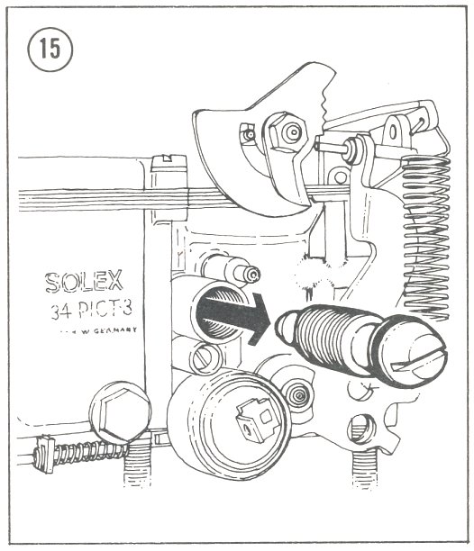
To perform this task, remove the carburettor (remembering to place a piece of rag in the inlet manifold to prevent any dirt or dust entering the motor, and later, not forgetting to remove same before refitting the carb). Dismantle the carb, and after drilling out the mixture screw, clean all passages of dirt and metal shavings. Set the carb up in a drill press, in order to drill out the mixture screw on its centre-line. If a drill press is not available, secure the carb in a vice, but place some aluminium or copper over the steel vice jaws to prevent carb damage. Enlist someone with a good eye to assist while lining-up the drill. It's best to drill a 3 mm diameter hole first, followed by a 6 mm hole. The latter will produce a hole larger than the conversion mixture screw base, thus allowing for the adhesive.
If one half of the mixture screw head is broken off, you will need to remove the other half, as the drill will kick off to one side. Breaking the screw head off may not be easy, but using a screwdriver as if adjusting the screw will usually twist the head off. Use the 6 mm drill first, marking the centre of the screw, then drill the 3 mm hole - but don't use too much pressure towards the bottom of the hole, as you could wedge the point of the mixture screw into the seat. If this does happen, locate the carb drilling onto the opposite side, removing the aluminium plug and, using a small punch, push the mixture screw out. To prevent this from happening, use new drills and mark the drill 24mm up from the end. This gives a clear indication of the approaching end of the threaded section.
With the mixture screw now drilled out, clean the carb and again, don't forget the metal shavings. This can be done with compressed air but, if not available, there are a number of aerosol carb cleaning sprays on the market that will be suited to the task. Remember to choose one that is ozone friendly.
Test fit the conversion mixture screw to the carb, turning the mixture screw until the base flange just lifts off the carb. It may be best to do this without the spring in place. The distance between the conversion mixture screw base flange and the screw head should be greater than the length of the fully compressed mixture screw spring. If not, you will have to keep removing metal from the top of the mixture screw hole on the carb until this measurement is obtained.
Using Araldite, glue the conversion mixture screw base to the carb. The base will be correctly located if it is glued in place while still attached to the mixture screw. After allowing ample time for the Araldite to cure, reassemble the carb using new gaskets and then refit the vehicle.
When fitting the mixture screw, turn the screw in until it comes to a stop, then reverse it 2.5 to 3 turns. The motor should run and idle on this setting. Placing a small amount of clean fuel in the carb bowl will assist the initial start-¬up and reduce the amount of cranking required.
All that now remains is to start the engine and adjust the carb. For best results, wait till the automatic choke is fully open and the engine has built up some heat. Adjust the idle to 850 rpm, plus or minus 50 rpm, and the mixture to 1.5 (+ or - 0.02) CO. If you don't have access to a CO gauge, turn mixture screw in till engine speed drops, then out till reaching fastest obtainable idle. Reset idle speed.
Big, Bad and Beautiful
By Richard Holdener
August 1997
Over-carburation is one of the most common problems with street motors. The thinking is that if 40mm is good, a 48mm must be even better. By now, most people realise that using a larger carburettor than the motor needs will actually result in less power. While street motors generally need less carburetion, the opposite is true with full-on race motors. The combination of lots of compression, displacement and rpm make these motors a natural for big-bore carburettors.
While a street VW motor that makes 80 kW is a pretty stout piece, we're talking about feeding race motors that make twice as much power as a healthy street piece. Drag race motors operate under a whole different set of rules than a typical street motor. A drag race motor is typically built to make maximum horsepower in a specific power band. A motor that revs to 9500 rpm is not likely to provide 150,000 trouble-free km on the street. Likewise, an ultra-reliable street motor isn't going to rip off a string of 10-second quarter-miles.
Now that we have covered the difference between a street motor and a race motor, how do we go about feeding a nasty race engine?
Before we can go into what makes Gene Berg's 58mm Webers tick, let's join Sherman and Peabody for a trip in the 'Way Back Machine'. Back in 1992, Gary Berg was running a Bug in the PRA Super Street class. The (race) motor was putting out some serious power, enough for him to motor down the quarter-mile track in just 10.55 seconds. Though most people would be happy with 10.50s, the folks at Gene Berg knew there was more left in the motor combination. The first thing they did was to look for ways to improve the air flow into the motor.
Though the 52mm carbs they were using had worked well so far, they speculated that the motor could benefit from even larger carburettors. Unfortunately, Weber only made a handful of the 58mm downdrafts for the Ford Indy-car program, and these were as scarce as hen's teeth and twice as expensive. No problem, ace fabricator Skylor Piper whipped up a set of prototype 56mm carbs using 48mm Weber bodies and lots and lots of aluminium welding rod. The results, though not pretty, were impressive. The motor responded with more power and Gary soon ripped off a 10.41 with the ugly pair of Piper specials. They knew that they were heading in the right direction. The next logical step was to manufacture their own big-bore carb bodies for racing applications. That's how the 58mm carb program got started.
While the need for speed helped spark the 58mm project, the carburettor is only part of the equation. Gene Berg also wanted to provide racers with a full line of performance carburettors based on the 48mm IDA Weber. Since Weber has all but gone out of the service and technical end of the performance carburettor business, Gene Berg has seen fit to take up the slack in the industry. Not only are the new carb bodies available in size ranging from 48mm all the way to 58mm. but also Gene Berg has the technical expertise to help racers maximise the carbs for their engine combinations.
One of the key to the success of the 58mm carburettors is the extensive research and development that has gone into them to optimise the fuel circuitry to suit the needs of a VW motor. As the large downdraft Webers were never designed to operate on the flat four motor, Gene Berg recognised this problem and made the necessary adjustments to fine tune the fuel delivery to the increase in air flow. One example of this is the series of sail holes at the base of the carburettor bore. These holes help provide a smooth idle and transition to the main jet circuit for a smooth power delivery.
Part of the success of the 58mm carburettors is due to the use of many stock Weber internals. The 58mm carbs use the standard 48 IDA bolt pattern, so they can be bolted to most 48mm manifolds, with porting to match the carburettor bore sizes. The 58mm carbs utilise either a 3/8-inch NPT fuel feed at the top of the carb body, or a 12mm thread in the standard location to accommodate a customer’s current fuel system. The use of a Gross Jet ball-type needle and seats allows the use of the stock Weber float assembly. The trick needle and seat ensures a constant flow of fuel under hard acceleration, eliminating the need for a large float bowl capacity. The Berg carbs also use standard Weber main and idle jets, emulsion tubes and accelerator pumps.
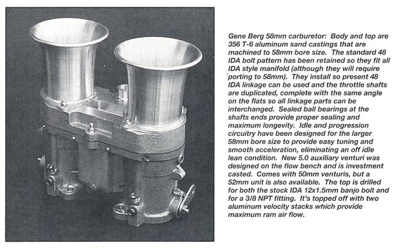
The throttle shafts are made from hardened tool steel and are installed with sealed ball bearings to ensure a leak-free carburettor. End shaft leaks are a common problem in the Weber family, especially after a few backfires through the carbs. The shaft ends have the standard flats to accept Weber linkage and throttle stops, making trackside installation and adjustment much easier. The butterflies also are hardened brass and machined for a precise fit. Like the 48s, the 58mm carbs can be operated by either a centre pull or overhead push down-type throttle linkage.
The standard Berg carb body can be built in bore sizes ranging from 48mm all the way to the bad boy 58mm size. The carb bodies are full of custom touches, including streamlined auxiliary venturis. These computer-designed booster venturis offer an aerodynamic shape and a modified 5.0mm fuel orifice (the stock 48mm uses a 4.5mm). The result of all this trickery is a venturi that starts operating at the lowest possible vacuum signal, making the carburettor ultra-responsive.
Another set of custom component used with the 58mm carb bodies are the 62mm velocity stacks. What better way to improve the air flow of the mammoth carbs than to stick a. custom 62mm velocity stack on top? Welded flanges help improve the strength of the stacks, while precision machining helps reduce the possibility of a surface mismatch between the carb and the stack. The result is a smooth transition for the air flow through the stack into the carburettor.
While all the trick componentry is nice, the real key question is do the carbs make more power? The answer is yes. The air flow bench shows that a 58mm carb with a 50mm venturi flows a whopping 11,810 litres per minute. Compared to either a 48mm, which flows only 7,870 L/min, or a 51.5mm, which flows 10,390 L/min, the 58s are the clear winner in air flow. To further stress how efficient these carbs are, the race motor was put on the dyno to test the power differences between the 58mm carbs and the old 56mm prototypes. With the 56mm carbs, the motor twisted the power needle all the way to 215 kW before running out of steam. The 58mm carbs upped the power ante even further, all the way past the old 300 bhp mark to 235 kW at 8500 rpm.
Is it coincidence that the current ET and MPH record holders in the Super Street class run Berg 58mm carbs? We think not.
Leaded or Unleaded
By Lance Plahn
October 1997
Well! The big question on most pre-1986 VW owners’ breath nowadays is, “What do I have to do to enable my vehicle to run on unleaded?”
Based on information supplied by the Federal Chamber of Automotive Industries and the Australian Institute of Petroleum Ltd., a list of pre -1986 vehicles that can run on unleaded petrol was compiled. The following Audis and VWs are on that list:
Audi 80 Fox - 1977 on
Audi 100 SE - 1978 & 1979
VW Kombi - 1978 & 1979
VW T3 Microbus - 1982 & 1983
VW T3 Transporter - 1984 on
VW Passat - 1977 on
VW Golf - 1977 on
However I would hasten to point out this list would only refer to vehicles with engines in original condition; that is, genuine valves and seats with stock compression ratio.
So what about those many other VWs not on this safe list? Let's first look at why the lead is in the fuel in order to understand the problem. It is there for two basic reasons: No.1. - octane enhancer, and No.2 - upper cylinder head lubricant.
Octane Enhancer:- A fuel's octane rating is a measure of it's anti-knock properties. If the octane is too low for an engine's compression ratio, the engine can ‘ping’ (pre-ignition, or detonation), possibly causing internal engine damage. This condition generally occurs at full throttle. Tetra-ethyl lead was originally added to petrol to stop pre-ignition (and thus boost the ‘octane rating’. Old ‘Super’ petrol (red in colour) had an octane rating of 97 (minimum), while standard unleaded petrol (yellow in colour) has an octane rating of just 91 (minimum). Some ‘mid-range’ unleaded fuels are 95-octane, while you have to buy more expensive ‘Ultra’ or ‘Optimax’ unleaded fuels to get an octane rating of 98. These fuels are not sold at every petrol station – not yet, anyway.
It’s important to understand that a higher octane petrol alone does not produce more power than lower octane petrol. It only prevents pre-ignition. However, a higher octane fuel allows a higher compression ratio to be used, which produces more power. High octane fuels were developed during WW2 for use in fighter planes, to counteract pre-ignition when higher compression and more supercharging was used. It was only by adding tetra-ethyl lead, and many other exotic additives, that octanes such as 100, and even 130, were achieved for aviation fuels. However lead is poisonous, so it is being phased out. Take out the lead, and petrol octanes drop back to 91, as in standard unleaded fuels. Modern cars are designed for this; old cars may not be.
To overcome the above situation in order to run successfully on U.L.P. you may have to do one or two things to prevent ping. Firstly, adjust the ignition timing to within a couple of degrees of specifications, or retard it further a few degrees. You could also recalibrate the distributor advance curve. Bosch 009 distributors only have one advance spring (light) but have provision for the second (heavier) spring. Secondly, lower the compression ratio to specifications, or a little lower. My experience reveals that most engines have by now had a number of overhauls, ultimately increasing the compression ratio. Every time you fly-cut or otherwise machine metal from your heads, you increase the compression ratio. To lower the compression you can use spacing shims either under the cylinder barrels, or between the cylinder and head. Water-cooled engines can use a thicker, or additional, cylinder head gasket.
Upper cylinder lubricant:- The lead acts as a lubricant between valves and seat faces to prevent premature corrosion and burnt valves. There are bottle products on the market, such as Valvemaster and Nulon lead replacements, which can perform the same duty in lead-free petrol. However for many engines these have to be purchased and added at every full-up, which increases cost and inconvenience.
The solution to this situation is simple (though may not be cheap) - replace valves and seats with items being compatible or suited to U.L.P. usage. This is really the only practical solution for engines with ‘soft’ valve seats in iron heads, such as 1960s and 1970s Holden engines.
Volkswagen engines, however, don’t need this. They have aluminium heads with hard valve seats, and will run perfectly well on unleaded petrol without any mechanical modifications, so long as any pre-ignition problems are also addressed. Remember that the USA went over to unleaded fuel in the 1970s, long before we did, and VWs have been running for years on their petrol without difficulty. By all means buy and add ‘lead replacement’ bottles to your tank if you like (they won’t do any harm), but don’t be talked into expensive ‘unleaded’ conversions to VW engines. They already are.
Research shows the majority of vehicles doing high mileages on our roads are already running on U.L.P. If current trends continue, U.L.P. will take over from Super as Australia’s most popular petrol by 1998. There are varying industry predictions that Super petrol production will cease between 2000 and 2003.
It should be pointed out that apart from its health dangers, lead was also removed to enable vehicles to be fitted with a catalytic converter in the exhaust system to further reduce harmful exhaust emission. Leaded fuel merely ‘poisons’ the cat, rendering it ineffective after only a couple of tanks. Hence running your pre-86 vehicle on U.L.P. will not be as environmentally friendly as a post-86 vehicle fitted with a (compulsory) cat, which are designed and built to meet to-days tough pollution laws, but it will still be cleaner than using leaded fuel.
Running your VW on U.L.P. will enable you to keep driving your classic VW well into the twenty first century, and be a little kinder on the environment at the same time. If however you are uncertain about unleaded fuel and wish to move over gradually, you could fill up with U.L.P. on each alternate fill (with normal leaded Super on the other fill), providing there is not a ping problem. And once Super is discontinued altogether in a few years, you will be ready.
Remember that the octane of your unleaded fuel – 91, 95 or 98 – reflects its anti-knock properties, and therefore additional benefits for higher compression engines.
By using expensive premium unleaded petrol in a low-compression engine - say a pre- ‘86 Kombi or an old Beetle - will offer little or no gain for the extra cost. On the other hand, a 98-octane fuel offers improved performance and fuel economy in the Golf GTI recently released in Australia. It has a modern engine management system and higher compression to get the most out of a higher-octane fuel. In fact, VW recommends a minimum of 95 octane on its modern Australian-spec vehicles.
Automatic choke adjustment
By Ron Van Ness
September 2000
With the weather changing in most places, this info should be beneficial to a few auto choke-carburetted VW drivers out there, ones who might only have the Muir manual to go by.
First, disconnect the wire to the choke and remove the throttle return spring that goes from the throttle lever to the arm atop the carb.
Loosen the three screws around the plate that holds the choke down so that they no longer screw into the carb body – they will still be held loosely by those white nylon washers. When you have loosened all three you can gently pull the plate back with all the screws/washers attached and put it somewhere safe, being careful not to drop those washers and screws.
The element should look just like an old clock spring to you and there should be no distortion in the spring. That is, the element should wind around itself with smooth curves and evenly. If it appears bent/mangled or if it falls out of its housing, you know you'll need a new choke.
Now to adjust the choke. Do this with the engine cold! You'll notice when you look at the element it terminates in a little hook. That hook grabs the lever that moves the shaft/butterfly valve on top of the carb. Loosen the clamp holding the rubber tube from the air cleaner to the top of the carb, pull the rubber end off the carb throat and push it back out of your way. For a visual aid, put a hand held mirror over the carb throat so you can see the valve and move the lever that the choke controls. You'll see that when you move the lever down (assuming you properly engaged the element hook on the lever) the butterfly valve closes all the way. With the choke removed move the lever back and forth. The shaft should open and close the butterfly valve smoothly. If it does not, you have a bent shaft or worn bore on the carb, and that could be the cause of your problem. Getting a good top half off a used carb (it's the bottom end throttle bushing that tends to wear out more than the top) will quickly solve the problem.
Now put your choke back in place on the carb (forget about the plate/screws for now) and place it on so that the element hook will engage the lever when you push it in place. Watch the mirror and move the choke slightly forward and backward. You'll notice that the valve opens (choke rotated back) and closes (choke rotated forward). You want to set the choke so that the valve just barely closes for cold weather. To achieve this, gently turn the choke so that the valve just closes and then back it off just a hair so the valve is open a sliver. You'll have to tweak this initial setting a bit to get it just right - I'll describe that later - but this will get you in the ballpark initially.
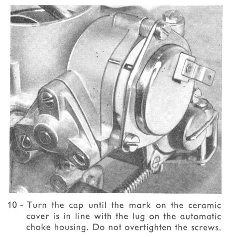
You’ll notice that there is a dot stamped on the choke disk that lines up between 3-4 ridges on the carb body. Lining up this dot with the lower ridge (choke more closed) is a good setting for cold winter days that require longer warm-ups. Lining the dot up with the upper ridges will open the valve which is better for warmer days when you don't need the choke to engage the lever for very long. The element does not expand/retract based on engine heat (though engine heat affects it somewhat), but primarily on the duration of the electrical current heating it from the coil wire, so even on a warm day you'll have to wait almost as long for the choke to spring open the same amount. That's why you have to manually adjust its position when the climate changes.
If you find when you turn the choke element so that it just closes the valve that the dot does not line up at all with the ridges on the carb body (i. e. it's way below them) you have a distorted element and you'll have to replace your choke. In fact you probably already noticed this in your visual inspection – it could've been the result of someone overturning the choke in the past, or the element has simply worn itself out of shape.
If the choke looks good and you position it so that the valve is just cracked open, you can put the plate/screw assembly back over the choke and tighten the screws, being careful not to disturb your setting. Don’t put a lot of pressure on those screws. Just enough to snug them down to hold the choke in place. The nylon will compress a little giving a good fit. It's tempting to give them an extra turn, but you will strip the housing if you are too zealous. If you strip the threaded housing the quick solution is easy: just find a slightly bigger screw at a hardware store and thread it in. But you don't want the hassle of potentially damaging the threads on the carb body so go easy on them and you won't have a problem. Reinstall the spring on the throttle arm and reconnect the choke wire.
You'll probably have to make adjustments to your choke setting to zero it in after observing a few cold start warm-ups. Before starting the engine, press the accelerator pedal once - this will pull the throttle arm back and the choke element will act as a spring to snap the butterfly valve closed and set the step cam. For your first warm-up, you might notice that your engine rpm is high a little longer than it should be, or it idles too low and stalls when cold. In this case, your choke setting needs some tweaking. This is because the choke not only closes the butterfly valve; it also controls the stepped cam on the left side of the carb that will affect your idle speed.
When your engine is cold, notice on which step the throttle arm screw rests. The higher the step, the higher the idle, the longer the warm-up time before the choke disengages. If your engine idles high for a little too long, just remove the throttle return spring and loosen the three choke screws a bit and gently slide back your choke a hair - now the idle screw should rest on a step lower. Tighten the screws and reinstall the spring. Reverse this procedure if your choke does not hold the step cam at a high enough rpm (your engine will stall when warming up at idle because the choke element will disengage the lever too soon). You will eventually get it just right.
Use both the step cam and the dot on the choke relative to the ridges on the carb body as your guides for positioning the choke, and if you get really good at it, you can tweak the adjustment a tad even when the choke is warm so that for the next cold startup, your choke will be set perfectly.
Another thought: Look at the step cam and you'll see a little slot cut into it - a roll pin should be visible. This pin limits the rotational travel of the cam and is secured in the carb body. If the roll pin has vibrated itself out and is no longer there, your step cam could fall back and make idling cold difficult. If it's missing you just have to tap a new roll pin in place.
Also, make sure the wire going from the coil to the choke is actually connected on both ends - that might be your only problem if your choke is set properly. Check the wire condition from end to end – the engine bay gets hot and the insulation gets stiff and perishes after 40+ years. Likewise the original push-on connectors can come loose or fall off over time. Make up a new black wire with new soldered ends if necessary. You should always keep spare lengths of different coloured wire, and quality male/female push-on connectors, in your VW toolbox.
You may have to tweak the choke a few times a year if you live in a region that gets
seasonal changes so that your morning warm-up is hassle free. Don't disable your choke as some advocate; Volkswagen designed it and included it to make your VW work better. Just keep it properly checked and adjusted.
Good luck!
Octane number explained
By Rob Aussiebug
April 2003
The octane number of a petrol is NOT a measure of its hotness or coolness in the burning process, and it is NOT a measure of how 'powerful' it is. The octane number is simply a measure of how good the petrol is at resisting detonation (knocking/pinging).
The internal combustion engine is - in simple terms - a gas pump. The higher the gas pressure inside the cylinder, the more 'push' there is on the pistons, and this means the higher the power output will be.
We create this pressure by heating a cylinder full of air; and we do this by adding a little petrol to the air and igniting it with a spark.
The engineers aim to get the highest possible pressure without creating uncontrolled burning of the petrol.
Detonation (pinging/knocking) occurs after the fuel is ignited by the spark plug, but before the flame front has finished moving across the cylinder to burn all the fuel/air mixture (don't confuse it with pre-ignition, which occurs when the fuel is ignited before the spark occurs).
The reason why detonation occurs relates to the nature of petrol. Petrol is a mixture of different hydrocarbon molecules, and some of these molecules decompose more easily than others when heated under pressure.
We ignite the fuel/air mixture with a spark, and the flame front starts moving across the cylinder. This increases the temperature and pressure of the remaining fuel/air mixture, which starts to decompose before the flame front reaches it. If this decomposition produces 'auto-ignition' compounds (those which will start burning without a spark); you end up with an uncontrolled over-rapid burning of the remaining fuel, which sets up an opposing pressure wave in the cylinder. This uncontrolled burning and the opposing pressure wave produces the characteristic clicking/pinging sound of detonation, and results in the piston getting a 'hammer blow' instead of a steady push.
You can test for detonation/pinging quite easily. Get the engine up to normal running temperature, and drive normally up a slight incline in fourth gear at 50 km/h. Then floor the throttle. If you hear harsh, uneven clinking, tinkling or pinging sounds from engine, that’s detonation. You need to either adjust the timing (reduce the advance) and/or use a higher octane fuel. These hammer blows can quickly destroy the engine.
Higher-octane fuels are better at controlling the decomposition into auto-ignition compounds than lower octane fuels. They do this in several ways - by interfering with and reducing the actual decomposition, or by chemically reacting with the decomposing gasoline so less auto-ignition compounds are formed.
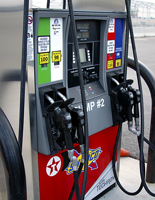
There are three main sources of heat inside the cylinder, which contribute to the decomposition of the fuel: -
1. The residual heat in the heads, cylinders and pistons. The VW engine is air-cooled and runs hotter than its water-cooled cousins, so more residual heat is present.
2. The heat produced by the ignition of the fuel itself. This depends on the nature of the fuel, and on the fuel/air mixture - rich mixtures burn a little cooler, lean mixtures burn hotter.
3. The heat of compression before the spark. Compression of a gas raises the temperature of the gas. We want this to happen, because the higher the compression, the higher the pressure rise after the fuel is burned - giving us more power.
The first two items are largely fixed, and not easily adjusted. Altering #1 would require extensive alterations to the engine design. Altering #2 would require a change in the fuel chemistry, which is not even in the hands of the engine designer.
#3, the heat of compression (compression ratio) is easy to adjust in the design of an engine, so this is the one used to match an engine with the fuel it will be using.
It's all a balancing act, and because the air-cooled engine runs hotter (more residual heat), you need to limit the amount of additional heat produced in the cylinders prior to ignition (lower compression ratio). Air-cooled VW engines therefore use a slightly lower compression ratio than water-cooled cars using the same octane rated petrol.
The octane number came about as a result of research carried out in the 1920s and 30s by Sir Harry Ricardo (‘The Internal Combustion Engine’ 1925, and other books) and Charles Kettering (of Kettering coil ignition system fame). Ricardo had previously developed an ingenious variable compression test engine when he was asked to develop an engine for the British WW1 tank in 1916, and this test engine was used in his subsequent research. The British War Ministry used to order fuel by Specific Gravity and the fuel they gave him to use in the tank he assessed (years later) as having an octane rating of about 45. His tank engine was limited to a compression ratio of about 3.5:1 to cope with this poor fuel.
Incidentally, this engine was extremely innovative for its day, and was utterly reliable - so it also got used as a stationary (generator) engine by the British army for their field stations all over France, and by the British Navy for its patrol boats, as well as about 12,000 tanks. The Army and Navy loved it because it would run on just about any liquid fuel - it would even run on a kerosene/gasoline mix if that was all they had! It was just as happy (but gave no extra power) on high-grade aviation petrol.
It was discovered that Iso-Octane had a very high knock resistance, but Heptane had a very poor knock resistance. Because these two compounds are very similar in other respects, they made a useful comparison point for gasoline. So the octane number is a comparison with a mixture of Iso-Octane and Heptane. 91 Octane is equivalent to mixing 91% Iso-Octane with 9% Heptane.
The discovery in the late 1920s that certain lead products enhanced the anti-detonating characteristics was a revolution in fuel design, as engines could be designed to operate at higher compressions for better efficiency. So petrols became ‘doped’ with Tetra-Ethyl Lead (TEL) or tetra-methyl lead to enhance their octane numbers.
Another useful feature of lead in petrol is that the burned lead products coated the hot exhaust valve seating area, and prevented a problem called Valve Seat Recession (VSR) which results in the exhaust valve 'eating' it's way into the head. With the less advanced soft cast iron heads of the day, this was a real bonus.
VSR is not a problem with VW engines, as they have hardened valve seats inserts in their aluminium heads. So the VW engine can run on unleaded petrol quite happily, provided the octane number is high enough.
An additional feature of lead additives was that they provided a small but useful amount of lubrication to the valve stems. This was important in engines that had cast iron heads with the valve guides cut directly into the head metal. Most cars also required valve seals to prevent excess oil from dripping down the valve stems and causing a smoky exhaust, and so they had little engine oil available to lubricate the valve stems. TEL in the fuel provided a useful additional amount of lubrication - partially replacing the ‘missing’ oil based lubrication.
The VW engine has bronze alloy valve guides which do not require any lead based lubrication, and the design of the valves does not need valves seals, so they are lubricated very well from the splashed oil on the spring end of the valves. The VW engine does not require leaded fuels for valve stem lubrication purposes.
In the years since, lead has been removed from fuels because it pollutes the atmosphere, and when ingested by animals, builds up and causes health problems.
Petrol that is high in aromatics has a high 'natural' octane rating and so needs less additives to increase the octane rating. Unfortunately, the aromatic compounds are also those most responsible for atmospheric pollution, so these compounds are being reduced in gasoline in many countries. This creates another dilemma - how to increase the octane rating without lead additives, and with reduced aromatic compounds in the fuel?
A number of other chemical compounds called Oxygenates have been developed to enhance the natural octane number of petrol. The most common one used is Methyl Tertiary Butyl Ether (MTBE). Other compounds include TAME, ETBE, Methyl Alcohol and Ethyl Alcohol (Gasohol). But MTBE and the other oxygenates contains ‘used’ oxygen, so cars using oxygenates fuels burn MORE fuel (because there is less 'fuel' in the fuel) and this increases pollution anyway.
And there is a second effect here too - carburettor cars like most VWs cannot adjust the fuel/air mixture 'on the run' like computer equipped fuel injected cars can, so they run lean when run on oxygenated fuels. This is because carburettors meter out a volume of fuel into the intake air; they can't measure the amount of 'fuel' in the fuel. Lean burning creates more heat in the cylinders, and this 'excess' heat raises the octane number needed.
It's a vicious circle, so if you can avoid using oxygenated fuels - do so. If you have to use oxygenated fuels, you may improve the car's performance by using a slightly larger main jet in the carburettor. Doing this brings the mixture back to the correct setting, which helps reduce the extra unwanted heat in the engine, and reduces the likelihood you'll need a higher than normal octane gasoline to compensate. And if your engine is due for a rebuild, and you have to use oxygenated fuels, consider using a slightly lower compression ratio.
Sir Harry Ricardo used the 'research' method of measuring the octane number using a constant speed (1500 rpm) engine in laboratory conditions. This is the RON - Research Octane Number. The other method is the MON - Motor Octane Number, which uses a harsher test regime more closely, related to road conditions. So the MON is usually lower than the RON is.
Often you may see the octane rating quoted as (R+M)/2. This means an average of the two methods is used to give the fuel a number. This number method is often called 'pump octane' in the US.
The 1200 VW engine running around 6.6 – 7.0:1 compression ratio needs a minimum of 87 octane (RON). The 1500/1600 engine running around 7.5:1 compression needs 91 octane (RON) or higher. Using a higher octane petrol in an engine designed for low octane WILL NOT increase it's performance - the octane number is a MINIMUM needed to eliminate detonation, and that's all it is.
I have a 1500 VW with unmodified heads running 1600 barrel and pistons. This has raised my compression ratio from 7.5 to 8 (more fuel/ air mix squeezed into the same headspace). It was originally designed to run on 91 RON (about 87 'pump' octane) but now prefers at least 93 RON. If I were to increase the capacity more without modifying the heads, I would need spacers under the cylinders to lower the compression back to a reasonable number (usually around 7:1), otherwise I would need to run on Hi-Octane (95 RON in Australia where I live) to prevent detonation.
Oxygenates are bad news for carburetted engines, and if you have to use them, expect to increase your main jet to compensate for the reduced amount of ‘fuel’ in the fuel.
In 2002-2003 some Australian states started allowing ‘E10’ Ethanol blend petrol. As noted above, oxygenates like ethanol cause a carburetted engine to run lean. 10% Ethanol causes a 3.9% lean mixture (ethanol is 39% ‘used’ oxygen). But some petrol stations are adding up to 20% ethanol and not signposting the pumps - these stations are mostly in New South Wales. Southern Queensland and northern NSW have many BP stations offering 10% ethanol blend (called E10) and these ARE signposted. In South Australia and Western Australia, it is illegal to sell ethanol-blended fuels, and in Western Australia it is also illegal to sell MTBE blend fuels.
10% ethanol blend (E10) needs a main jet 2 sizes larger than a straight hydrocarbon fuel (for example, from a 125 to a 130; or 127.5 to a 132.5), to get the mixture back in to balance (stoichiometry). 20% ethanol blend needs a main jet 4 sizes larger, and will probably need a larger idle jet too. Fuel consumption WILL increase with these changes. But there are other reasons – water retention, corrosion, attacking rubber and plastic – that you should avoid E10 fuel altogether. Stick with normal 95 petrol, even though it’s more expensive.
Up until about 2001, MTBE was not an issue in Australia, but Woolworth's Petrol Plus outlets all over Australia (except Western Australia) have fuel with an average of 2-3% MTBE (most Petrol Plus fuel is imported from overseas - they don't get much fuel from Australian refineries). The Woolworth's web site is a little confusing because they also mention up to 7% MTBE (so does the average 2-3% mean none in Western-Australia and 7% on other states)???
Why the fuss? Well 2-3% MTBE is not going to bother your VW engine too much, but with 7% MTBE, your engine will be running just over 1% lean, which might be noticeable in some engines - especially those using the 34PICT-3 carburettor, which is generally set to run a little leaner than the smaller 30 and 28 series carburettors. So if you experience detonation - try changing brands and see if this makes a difference.
In conclusion, the octane rating is a measure of the fuel's ability to CONTROL the burning process (to prevent detonation); it is not a function of burning 'hotter' or 'colder'. And the higher the compression ratio (in the same engine), the higher the octane number needed. And finally – DON’T use E10 ethanol in an air-cooled Volkswagen. E10 is only suitable for modern fuel-injected VWs made after 1986.
VW’s FSI Injection
By Stephen Gillarde
August 2005
For well over a decade now, fuel injection has ruled supreme. And rightly so. Fuel injection dethroned carburetion because it performs better, provides crisper throttle response, improves fuel economy and allows much easier starting especially during cold weather. But the main reason why carburettors were scrapped in favour of fuel injection is because fuel injection produces much lower emissions.
Diesel v Petrol Injection
Petrol-powered engines with fuel injection have always used ‘indirect’ injection systems, which spray fuel either into the intake manifold or head ports. Diesel injection systems, on the other hand, use ‘direct’ injection and spray fuel directly into the combustion chamber (or prechamber).
Why the difference? Because diesel engines are compression ignition engines that have no spark plugs. Diesel fuel is ignited by extreme heat and pressure. This requires a very high compression ratio (20 to 1 or higher) in the cylinders, much higher injector operating pressures (up to 20 MegaPascals) to overcome compression pressures in the cylinders), and precise injector timing. Diesel engines are also unthrottled, which means engine speed and power are controlled by the amount of fuel injected into the engine rather than airflow.
Direct injection works in diesels because diesel fuel is actually a light oil that has a much lower flash point than petrol. Trying to run a diesel engine on petrol will destroy the engine in short order because petrol detonates when it sees too much heat or compression. Detonation causes a sudden rise in cylinder pressure that hammers the pistons with excessive force. A slow, controlled burn is necessary for proper combustion and to prevent engine damage.
Being able to inject petrol directly into a high compression spark-ignited engine should theoretically improve fuel economy and performance. But until recently, attempts to make a practical direct injection petrol engine have failed because of detonation and emission problems.
Petrol Direct Injection
Direct Injection appears to be the next generation of fuel injection for petrol engines. The reasons for this technology are legislative, and also include market requirements that drive the need for reduced fuel consumption, while at the same time, meet the increasingly stringent exhaust emissions regulations. Petrol Direct Injection can improve combustion efficiency and reduce engine pumping losses, both of which will result in improved fuel economy.
Mitsubishi in Japan was first to release a production ‘Gasoline Direct Injection’ (GDI) engine in 1996, which reportedly delivered 15 to 40 percent better fuel efficiency than an indirect multi-port injected engine. The engine also put out 10 percent more torque and met all emission requirements, including the ones for oxides of nitrogen (NOx) which are especially tough to meet. However this engine wasn’t used for export.
The Audi A3 was the first car sold in Australia with direct petrol injection, in May 2004. Volkswagen followed soon after with the Golf FSI in September 2004. To compare them, the old petrol 1.6 Golf offered 75 kW at 5600rpm and 148 Nm at 3800rpm, and achieved 7.5 L/100km. The new 2.0 FSI (Fuel Stratification Injection) produces 110 kW at 6000rpm, 200Nm at 3500rpm and a fuel consumption average of 8.0 L/100 km.
Performance-wise the FSI is the leader, with 8.0 seconds for 0-100 km/h. The 2.0 TDI follows with 9.3 seconds (a diesel!), the 1.9 TDI (11.1 sec) and finally the old 1.6 with 11.4 seconds. In general, better fuel economy up to 35 % is achieved with FSI when compared with conventional Multi-Point Injection systems. There is 10-15% more power to be gained.
Mitsubishi Motor Corp patented the term ‘GDI’ – Gasoline Direct Injection, but the basic technology is common to all makers. Daimler Chrysler AG uses the moniker ‘CGI” ([stratified] Charged Gasoline Injection). Ford named its system DISI (direct injection spark ignition) to underline the evolution of direct injection from advanced-diesel development programs.
Volkswagen AG calls their system ‘FSI’ (fuel stratified injection), benefiting from its TDI (Turbo Direct Injection) turbo diesel development dating back to 1989. Being VW enthusiasts, we’ll use the Volkswagen FSI name to refer to direct petrol injection systems.
The FSI engine runs on an ultra lean (40:1) air/fuel ratio at idle by using special injectors that produce a ‘stratified’ charge in the combustion chambers. Regular petrol fuel injectors produce a fine cone-shaped mist that's necessary to create a homogeneous air fuel mixture – one that’s mixed evenly throughout the combustion chamber. The high-pressure FSI injectors, by comparison, produce a very compact spray pattern that forms a swirling cloud of fuel particles. This, combined with a ‘reverse tumble’ airflow in the cylinders, creates a layered effect (‘stratified’ charge) of air and fuel in the cylinder that is rich in the immediate vicinity of the spark plug but is progressively leaner further out.
One of the keys to making this work is the way air is directed into the cylinders. Most engines have horizontal intake and exhaust ports so air and fuel enter past the intake valve, blow past the spark plug and swirl back around the cylinder in a circular path before being ignited. In the FSI engine the intake port is almost vertical. Air flows down from the top, enters past the intake valve and injector, flows down the side of the cylinder until it hits a cup shaped pocket in the piston dome that redirects it back up towards the spark plug. This ‘reverse flow’ arrangement, combined with relatively late injection timing in the compression stroke, allows the engine to handle very lean mixtures at idle without misfiring. When more power is needed, injector timing is advanced earlier in the compression stroke and more fuel is injected into the cylinder to create a more conventional fuel mixture.
Lean burn engines that produce exceptionally low carbon monoxide and hydrocarbon emissions have usually had problems meeting NOx (nitrous oxides) emission standards because elevated combustion temperatures increase the formation of NOx. But the FSI engine overcomes this problem by using more exhaust gas recirculation (up to 30 percent EGR flow rate) to dilute the incoming air, and a special blend of catalysts in the catalytic converter. The result is a 97 percent reduction in NOx emissions compared to a conventional engine.
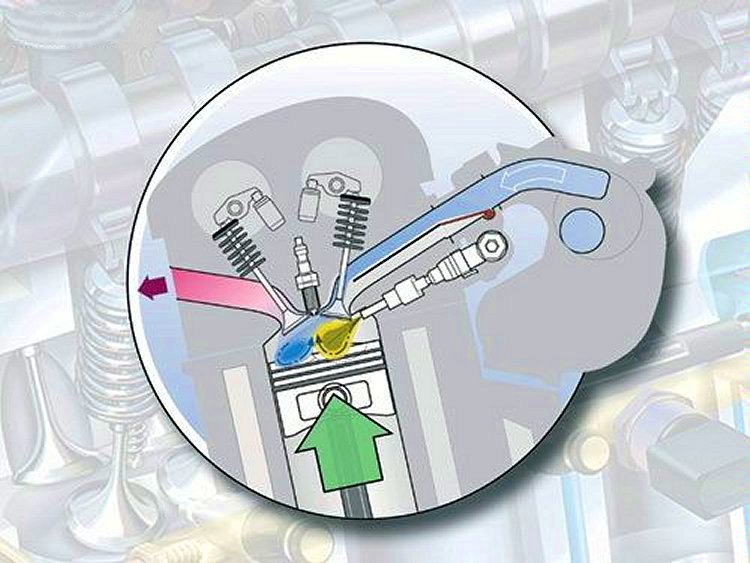
Direct Injection Operation Modes
The FSI combustion mode can be changed to help with cleaner tail pipe emissions. For example if excess O2 is required across the catalyst, then the mode can be changed to produce this. During cold starting or if the catalyst temperature falls, the engine can inject additional fuel into the expansion stroke and thus the high temperature exhaust gas, in which there remains substantial extra oxygen from the super lean combustion process. The ignition timing may also be changed. By retarding the ignition timing there is a concurrent increase in exhaust temperature. These strategies keep the catalyst within its cleansing operating temperature (approx 300 to 850 deg C).
There are up to six operating modes used in direct injection that allow the best possible adaptation for each and every operating state. During actual driving, the driver doesn't notice the change over between each of the operating modes since these take place without any torque surge:
1. Stratified mode
2. Homogenous mode
3. Homogenous lean-burn mode
4. Homogenous Stratified mode
5. Homogenous/Anti-knock mode
6. Stratified-charge/Cat-heating mode
Modes 4-6 are realised by double injection, and in modes 4 and 5 the first injection is triggered on the intake stroke and the second injection is done on the compression stroke - these two injection events create a homogenous lean basic mixture and a richer zone, which is easier to ignite around the spark plug.
1. Stratified Mode
Stratified mode operation can also be called ‘compression lean mode.’ An excess air factor is supplied to the engine, of between 20 to 40 to 1 APR (air fuel ratio - slightly lean to super lean). By comparison, the ‘ideal’ air fuel ratio for an old carburettor engine was about 14 to 1. The fuel is delivered on the compression stroke about 40 degrees before top dead centre.
FSI uses a tumble down air method (with the help of the charge motion valve) into the cylinder via the vertical intake port. The fuel/air mixture moves in a clockwise tumble direction and is then directed to a uniquely shaped piston top, which redirects it to the centre-mounted spark plug as a relatively rich mixture.
At this time the fuel has not thoroughly mixed with the available air, and is ‘stratified’ with the fuel being concentrated to the centre while the air is moved to the outer edges of the cylinder. This allows a relatively conventional ignition system to ignite the fuel completely and the flame propagates to the leaner outer areas of the cylinder during the burning process.
This greatly reduces HC emission as the fuel is kept away from the cooler cylinder liner and thus prevented from condensing back to a liquid and being exhausted as an HC emission to the atmosphere. The engine at this point is also running un-throttled through the use of an electronic throttle valve. This means that the engine torque is controlled by the amount of fuel delivered to the engine similar to that of a diesel engine. In the compression lean mode, considerable fuel saving is made which also equates to reduced CO2.
While extremely lean air fuel mixtures provide superior fuel savings there are some down sides when the engine is operating in this mode.
In lean burn operation the HC, CO2 and CO are greatly reduced but peak combustion temperature is very high, giving rise to excessive NOx production. To combat this FSI uses an extremely high tolerance of EGR (up to 30%) and a lean reduction NOx catalyst (countries with high sulphur fuel) or NOx trap in combination with a dual layer three-way catalyst (TWC). Because the FSI is so effectively controlled it can withstand some EGR during idling, and as mentioned up to 30% at other times. This would be difficult for a conventional MPI engine to achieve.
The advantage of this mode is that lower fuel consumption is achieved (15-20 %), by the lower charge cycle and cylinder wall heat losses. It is used in the low torque range and up to speeds of 120 km/h.
If the engine is operated in the Stratified mode for long periods of time, there would be a shortage of vacuum to operate the brake booster. To prevent this, there is a vacuum switch or pressure sensor fitted that sends this information to the Engine Control Unit (ECU) to change the operating mode (close the throttle valve) in order to supply brake booster vacuum.
2. Homogenous Mode
In this mode the fuel is injected into the intake stroke and forms a homogenous charge similar to that of a conventional multi-point injection engine. The distinct advantage of this point is the charge cooling effect, which results from injecting the fuel directly into the cylinder. This uses the same principal of latent heat (heat to change the state from solid to liquid) used with air conditioning refrigerant. Because the fuel changes its state from liquid to gas inside the cylinder, it absorbs a large amount of heat and thus reduces the cylinder temperature sufficiently to reduce engine detonation.
The compression ratio of the engine as a result can be increased to improve the engine’s thermal efficiency and fuel economy. Typically in the FSI engine a compression ratio of 12:1 to 13:1 is used, much higher than normal petrol engines.
This operating mode is the only one used in cases of high torque demand and high engine speeds.
3. Homogeneous Lean Burn Mode
This mode allows for a smooth transition during the switch over or between the modes, from stratified to homogeneous mode. Torque behaviour can be smoothed out during the switch over.
Less fuel is injected, and the lean mix is directed towards the spark plug by having the air intake restricted with the use of the charge motion valve. This results in a more stable combustion.
This mode creates an advantage in fuel consumption in the engine speed and torque range above the stratified mode.
4. Homogeneous Stratified Mode
This is the transition when the engine moves from a Homogenous to a Stratified mode.
During this mode, the complete combustion chamber is filled with homogeneous lean mixture. This mixture is generated by injecting a small quantity (75% of required fuel charge) of fuel during the intake stroke. Torque behaviour can be smoothed out during the switch over. Fuel is injected a second time during the compression stroke as a stratified charge, which leads to a richer zone forming around the spark plug. This stratified charge is easy to ignite by the spark plug and the burning mixture will then ignite the first lot of fuel mixture injected into the cylinder.
As in stratified mode, the intake port is restricted via the charge motion valve which aids in fuel transportation towards the spark plug.
5. Homogeneous knock protection mode
Engine knocking is the self-ignition and uneven combustion of the mixture in the peripheral zones of the combustion chamber, which can lead to engine damage.
To avoid this occurrence, this mode has a two stage mixing process that is used during low engine speed and high load. In this situation the fuel is injected on the induction and compression stroke during the same cycle. Also due to the cooling effect, the air density is increased, improving the volumetric efficiency.
The first injection (Lean Homogenous) is carried out on the intake stroke, resulting in a homogenous lean mixture with a reduced ignition quality in the combustion chamber. This reduced ignition quality resists the tendency for pre-ignition.
The second injection (stratified) has a cooling effect by vaporising fuel in the combustion chamber just prior to ignition.
Therefore the use of ignition retard to avoid knock is not required, and the use of a more favourable ignition advance point leads to higher torque from the engine. A knock sensor may be used during other operating modes.
6. Stratified Catalyst Heating Mode
This is a different form of dual injection (operates only for 30-40 sec.), which is used for two purposes – to quickly heat up the exhaust system during cold start and warm up, and to heat up the NOx Accumulator and initiate the desulphurisation process.
While this mode corresponds to the stratified mode, in addition the second injection is carried out on TDC or after TDC, and aids in the heating up of the three-way catalyst and the NOx accumulator to a very high temperature.
In the Desulphurisation Mode, the same principle is applied as in the Stratified catalyst- heating mode - to heat up the NOx accumulator to temperatures of 650°C and initiate the desulphurization. While the normal operating range is between 300-400°C, the air intake is restricted in this mode via the charge motion valve.
The FSI Fuel System
FSI uses same engine management sensors as the MPI system, although the FSI system consists of a high and low-pressure fuel system.
The low-pressure electric pump delivers fuel to the high-pressure pump at 300-500 kPa. Depending on the engine operating conditions, the high-pressure pump will generate the pressure which forces fuel into the fuel rail, where it's held until required by the injector. Fuel pressure is measured by a high fuel pressure sensor fitted to the fuel rail. This sensor feeds back the information to the ECU which controls the pressure regulator valve to maintain high pressure between 5,000-12,000 kPa.
The High Pressure Pump has a single barrel piston pump plunger is driven directly from the engine camshaft by means of a bucket tappet. Low-pressure fuel is drawn into the pump and pressurised before going to the fuel rail.
The Fuel Quantity Control Valve is electrically switched to maintain the correct amount of fuel delivery as required by the engine. When the valve opens it allows low-pressure fuel to enter the high fuel pressure circuit. The more fuel delivered to the top of the plunger the greater the fuel pressure achieved.
Any fuel not passed onto the high-pressure plunger is bled off from the quantity control valve via a helix and spill port in the high-pressure plunger to the return line. A damper located at the top of the pump assembly reduces fuel system pulsations and the likely hood of flat spots when the QCV opens and closes. The high-pressure pump is lubricated by fuel.
On the FSI system the Electronic Throttle Valve (butterfly) is controlled independently to the accelerator pedal position by the ECU, from inputs received. For example, when the engine is operating at low speed and low torque demand the ECU will fully open the throttle and will control the engine torque by varying the amount of fuel injected. This is used in conjunction with the EGR valve in the Stratified mode.
When the engine is running in lean mode (stratified), the ECU commands a very high EGR rate (up to 30%). Re-circulated exhaust gas reduces the combustion temperature and as a result lowers the temperature dependent on the NOx emissions.
To achieve in-cylinder injection the engine uses slightly larger injectors than conventional MPI electromagnetic injectors. The high-pressure injectors are fitted to the fuel rail, also known as common rail. The nozzle of the injector is located directly into the combustion chamber.
Injectors are triggered via the ECU using a special trigger module to generate sufficient voltage to open the injector. A booster generates 50-90 volts and enough amps – 10 - to quickly open the injector.
Compared to MPI, FSI has faster injection, improved precision of fuel spray alignment and better formation of spray. It meters and atomises the fuel extremely quickly and under high pressure in order to achieve the best possible mixture formation directly in the combustion chamber. A conventional EFI engine doing 6000 rpm has an injection pulse width of approximately 3.5 - 20 milliseconds, while an FSI engine uses just 0.4 - 5 ms. By comparison the blink of an eye takes 100 ms.
Injector Spray Modes
With the FSI engine using two combustion modes (Stratified and Homogenous), injection time and spray pattern changes to match the engine load. Varying plunger travel changes changes the spray modes.
When the FSI engine is operating with higher loads or at higher speeds, fuel injection takes place during the intake stroke. This optimises combustion by ensuring a homogeneous, cooler air-fuel mixture that minimizes the possibility of engine knocking. Similar to a conventional MPI engine, an air fuel ratio of 13 to 24:1 is used.
The FSI uses the Stratified Charge (Ultra-lean Combustion Mode) under most normal driving conditions, with tight loads under 3,000 rpm up to speeds of 120km/h. It operates in ultra-lean combustion mode for less fuel consumption. In this mode, fuel injection occurs at the latter stage of the compression stroke (as in a diesel engine} and ignition occurs at an ultra-lean air-fuel ratio of 30 to 40:1 - or up to 55:1 with addition EGR. Injection occurs from around 40° BTDC to 20° BTDC.
For further fuel savings, the Bosch engine management system has the capability to kill cylinder operation under low load conditions.
The Charge Motion Valve makes it possible to create a high charge intake air velocity by reducing the pipe diameter and geometry of the intake port. When the intake port is restricted (Stratified mode) the inducted air motion assures mixture transportation to the spark plug. Unrestricted intake port brings about a high charge level volume at high load (Homogenous mode). Because injection takes place in the intake stroke it can generate a good mixture preparation and therefore higher charge motion is not required.
The air inducted into an engine primarily contains Nitrogen (78%) & Oxygen (21%). The air is then mixed with petrol, which is Hydrocarbon (HC). In a perfect world we would have perfect combustion that would only leave the combustion by-products water vapour (H2O), Carbon Dioxide (CO2) and Nitrogen (N2), all of which are quite harmless.
As 100% complete combustion is not achievable we are left with five main by products: Carbon Monoxide (CO); Carbon Dioxide (CO2), Water (H2O), Hydrocarbons (HC) and Oxides of Nitrogen (NOx).
CO is a colourless and odourless gas. It is also extremely poisonous as it removes the ability of blood to carry oxygen. Carbon monoxide is formed when carbon burns with insufficient air.
CO2 is also a colourless and odourless gas, but it is not a pollutant - in fact it is vital to life on Earth. It is produced by respiration, and consumed by plants during photosynthesis. It is used extensively in industry as dry ice, and fizzy drinks, fire extinguishers etc. It is released by volcanoes and makes up a trace - 0.0004% - of the atmosphere.
Water (H2O) - a compound of hydrogen and oxygen.
Hydrocarbons (HC) are compounds of hydrogen and carbon, many of which can be burned to produce energy. Methane is the simplest hydrocarbon. Petrol is a more complicated carbon fuel. Since the combustion process in the cylinder is never 100% complete, some unburnt HCs are left in the exhaust. Sunlight breaks these down to form oxidants, which react with oxides of nitrogen to cause ground level ozone, a major component of pollution.
Oxides of Nitrogen (NOx) - Nitrogen and Oxygen together make up 99% of the air. When combustion temperatures are above 1,370 degrees Celsius, some of the Oxygen and Nitrogen combine to form NOx. In presence of sunlight, HCs and NOx join to form smog.
Catalytic converters were introduced to reduce harmful emissions. They initiate chemical reactions to take the CO, HCs and NOx out of the exhaust.
Early catalytic converters were a pellet-type, containing a bed made from hundreds of small beads, coated in precious metals. They were heavy, expensive and inefficient. The later monolithic type uses a honeycomb ceramic block.
The converter beads or ceramic block are coated with a thin coating of platinum, palladium, or rhodium, and mounted in a stainless steel container.
A two-way converter removed CO and HCs. Later three-way converters were introduced to remove CO, HCs and NOx. A three-way cannot remove all NOx, especially with exceptionally lean mixtures that are seen when in the Stratified mode.
The three-way converter has the same coatings as the two way converter, platinum and palladium (used to treat CO and HC) with an additional coating called rhodium, used to deoxidise NOx into nitrogen and oxygen.
As exhaust gas flows through the converter passageways and contacts the coated surface, the catalytic chemical process is initiated once temperatures are high enough. As exhaust and catalyst temperatures rise, the following chemical reaction occurs.
Oxides of nitrogen (NOx) are reduced into nitrogen (N2) and carbon dioxide (CO2) via the Rhodium coating. Hydrocarbons (HC) and carbon monoxide (CO) are dissociated and oxidised to create water (H20) and carbon dioxide (C02), via the Palatinum/Palladium coating.
Cerium promotes oxygen storage to improve oxidisation efficiency. Unleaded fuel must be used in engines with catalytic converters, otherwise the lead in the leaded fuel coats the catalyst and makes it ineffective. Apart from ruining the catalyser (requiring its replacement at a Volkswagen dealer, it is also illegal in Australia.
As mentioned, the Stratified mode operates a lean mixture of 30 - 40:1. As a result a lot of heat is generated, and consequently high NOx levels are generated. During lean burn operation it is impossible for the normal three-way catalytic converter to completely convert all the NOx that has been generated during combustion.
In the FSI system there are two catalytic converters to treat the emissions. The first one is the three-way converter, and the second one is the NOx accumulator.
In addition, the sulphur in petrol can create a problem to the accumulator type catalytic converter. The ideal sulphur content used in fuel for FSI engines should be less than 30 ppm. This will require assistance from the fuel companies in Australia to reduce this amount, as they currently produce a sulphur content of 500 ppm for ULP. Another possibility is the development of a new durable lean NOx catalyst.
Currently PULP is 150 ppm. ULP should be at 150 ppm by 2005, and all petrol should be at 50 ppm by 2008.
Sulphur contained in exhaust gas reacts with barium oxide (accumulator material) to form barium sulphate, and over time the accumulator material becomes less effective. Barium sulphate is resistant to high temperatures, and for this reason is only degraded to a slight degree during NOx regeneration.
As mention previously the Stratified Cat Heating mode is used to raise exhaust temps by injecting once in the compression stroke and again in the combustion (power) cycle. The fuel injected at this point combusts very late and therefore heats up the exhaust system to temperatures in excess of 650°C, as this temperature is required to initiate the desulphurisation.
Spark plugs are constructed with a platinum centre electrode and a composite ground electrode such as a copper core electrode inserted inside the platinum ground electrode. These provides stable combustion during lean mixture operation.
Coil-over-plug ignition systems are also used, which provide a very high voltage spark as compared to manifold injection.
What fuel is safe to use in my VW?
By Phil Matthews
August 2006
From January 1st 2005, Australian oil companies ceased supplying Lead Replacement Petrol (LRP), potentially panicking thousands of pre-1986 car owners who have relied on lead replacement fuel (LRP) for their leaded petrol vehicles.
“No-one need panic,” explains Chris Pascoe, an expert in fuel substitutes and additives. “There's a simple and effective solution which can protect your engine even better than LRP. The reason we had lead in petrol in the old days was that it was a cheap way for manufacturers to protect their engines and for oil refiners to boost the octane rating of their petrol to meet the requirements of higher performance engines. Lead oxide deposited on valve seats and formed a layer that cushioned the valves and seats against damage.
“But you don't need lead to do this. Quality lead substitute additives can do the same job,” Chris Pascoe explains. He is Technical Director of Nulon Ltd, a highly regarded Australian company which produces a range of fuel additives such as Lead Substitute, which makes normal unleaded petrol (ULP) safe for use in all vehicles that were designed to operate on leaded petrol (pre 1986), and avoids the need for costly cylinder head modifications. Chris also happens to be an air-cooled VW enthusiast and has recently finished a complete body-off restoration of a 1974 Beetle Karmann Cabriolet. His wife Heather uses a 1972 Superbug as her daily driver.
“The important thing for pre-86 car owners to watch out for is that whatever fuel additive they choose to use in their car must meet the stringent and demanding requirements of Australian Standard AS4430.1-1996, for engines designed for leaded petrol to operate safely on unleaded petrol. This Standard was developed to protect the consumer, so use it as a guide.
“Nulon Lead Substitute is made from a blend of oils and minerals including potassium, which provides the cushioning and lubrication that valves need. It's cheap and all you do is add one ml for every litre of unleaded fuel when you fill up.”
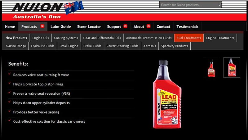
And which is the best petrol to use? Chris Pascoe explains it simply. “Most pre 1986 car engines were designed to run on ‘super’, 97 octane petrol, whilst standard unleaded is only 91 octane. By purchasing PULP 96 - 98 octane petrol and adding Nulon's Lead Substitute, consumers will get better performance, no more pinging and all the valve seat protection their leaded engine requires. As air-cooled VWs run a low compression engine, many will operate happily on 91 octane ULP, without the need to retard the ignition timing. The best thing to do is experiment with both types of petrol. If your engine operates happily on ULP, you would be wasting your money using PULP.”
On 1 January 2002, leaded Super petrol became no longer available in Australia, which meant that vehicles produced prior to 1 January 1986 (all of which were designed to run on leaded petrol) had to use either ‘unleaded petrol’ (ULP), or ‘lead replacement petrol’ (LRP).
LRP was simply Premium Unleaded Petrol (PULP) to which the refineries included an additive to provide Valve Seat Recession (VSR) protection. Lead (or more accurately, tetraethyl lead) performed two functions in petrol.
Firstly, it boosted the octane level of the petrol, which reduces the petrol's tendency to pre-ignition. This meant that refineries could reduce the cost by producing relatively low octane petrol and by simply adding lead the octane was increased to a satisfactory level to meet the requirements of evolving high compression engines.
Secondly, as the fuel was burned, lead oxide was deposited on the valve seats, which provided a cushion to protect the valve seats. Many pre-1986 engines were high compression and had cast iron cylinder heads. The valve seats were simply cut into the soft cast iron. Without the protection provided by the lead oxide deposits on the valve seats, the valves (through continually pounding shut) would eventually recede into the soft cast iron seat. The result was that soon the valves could not close properly and the exhaust valves would ultimately burn out. All engines produced for the Australian market since 1st January 1986 have been fitted with hardened valve seats to avoid VSR. All of these engines, of course, run exclusively on ULP.
Which cars must use a lead substitute? Any engine that has a cast iron cylinder head and is not fitted with hardened valve seats.
But what about my air-cooled VW? An engine is at greatest risk of VSR when it is heavily loaded, or at sustained highway speeds. This is due to greater heat being produced in the combustion chamber under such conditions. True, air cooled VW engines are fitted with aluminium cylinder heads, which in turn are fitted with hardened valve seats. The problem is that both ULP and PULP burn at higher temperatures that than leaded petrol did. This places VW valve seats at considerable risk. Also there is no information available that confirms exactly how hard the valve seats are. The fact that VW engines are air-cooled also puts them at greater risk as they cannot dissipate heat from around the exhaust port area as well as a water cooled engine can. Many pre-1986 European and Japanese engines which were fitted with aluminium cylinder heads and hardened valve seats, also will not operate safely on ULP, or PULP for the same reason, valve seats are not hard enough.
If you wish to run an engine on ULP or PULP and are unsure of the safety of doing so, always check with the vehicle manufacturer, otherwise severe damage could occur. If in doubt, use PULP plus Nulon LS to avoid any risk. LRP was only ever an interim measure and was always slated for phasing out.
What about in-line fuel catalysts? Chris says, “I have investigated the theory behind the many such devices on the market and have not seen any industry standard test results supporting their claims. They are very expensive and without supportive evidence of their performance, I personally would not be relying on such a device to protect any of my vehicles.”
Nulon Lead Substitute (LS) uses the latest and safest technology to provide unsurpassed valve and valve seat protection. Nulon LS can also be used in unleaded vehicles where additional upper cylinder lubrication is required. LS is safe to use in all brands of ULP and PULP for an indefinite period of time. Nulon Lead Substitute has been tested to, and passed, the stringent and demanding requirements of Australian Standard AS4430.1-1996, ‘Engines designed for leaded petrol to operate on unleaded petrol.’ Nulon LS also provides upper cylinder lubrication. Nulon LS has proven to be safe to catalytic converters and all engine and fuel system components.
There are numerous products on the market that claim to provide protection that will allow old leaded engines to use unleaded petrol. The above Australian Standard is to protect consumers. So, beware of any similar product that has not been tested to, and passed the requirements of the standard.
Nulon LS allows people to go to a normal petrol station, fill up with unleaded petrol, add the product and drive away normally. Nulon LS is not expensive, has been tested and proven to protect valves and valve seats. It puts the consumer in control of what goes into the fuel system of their beloved old car and reduces exhaust valve burning, valve seat recession, helps to clean upper cylinder deposits and will not harm catalytic converters or oxygen sensors if the treated fuel is used in post-1986 engines.